


Reference
PS280 & PS283 User Manual
15
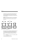
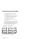
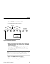
4. Set both variable supply CURRENT controls to midrange.
5. Set the AMPS/VOLTS switches for both power supplies to
display volts.
6. Turn on the POWER to the PS280 or PS283. The display should
read 0 V for both variable power supplies. An external meter
connected across the load or load terminals should read –5 V.
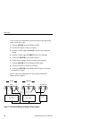
7. Turn the POWER off to the PS280 or PS283 again.
8. Connect the device or devices to be tested.
9. Turn on the POWER to the PS280 or PS283 again. Adjust the
voltages as needed.
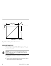
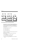
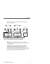
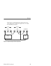
Figure 6 shows the PS280 or PS283 connected to produce separate
outputs of +5 V from the FIXED power supply, 0 to +30 V from the
slave variable power supply, and 0 to –30 V from the master variable
power supply. In this configuration, the red output terminal of the
master variable power supply is the negative reference terminal
because it is directly connected to the ground terminal.
Load 3
Load 2
0 to 2 A (PS280)
0 to 1 A (PS283)
0 to +30 V
0 to –30 V
Load 1
5V
0 to 3 A
0 to 2 A (PS280)
0 to 1 A (PS283)
5V FIXED 3A
-+GND
-+GND
SLAVE MASTER
Figure 6: Independent Ground-Referenced Split Application