


Reference
14
PS280 & PS283 User Manual
5V FIXED 3A
-+GND
-+GND
SLAVE MASTER
Load 2 Load 1
0 to 2 A (PS280)
0 to 1 A (PS283)
–5 V
3A
–5 TO +25 V
Load 3
0 to 2 A (PS280)
0 to 1 A (PS283)
–5 TO +25 V
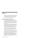
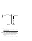
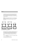
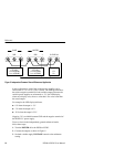
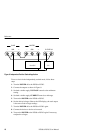
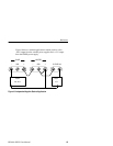
Figure 5: Independent Common Ground-Referenced Application
In this configuration, each of the variable power supplies can be
varied from –5 V to +25 V (+30 V overall). The GND post becomes
the relative negative terminal for both variable outputs. Because the
variable power supplies are referenced to –5 V, the LED display,
when set to display volts, shows a value that is five volts lower than
the actual output.
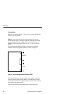
For example, the LED display indicates:
H 0 V when the output is –5 V
H 5 V when the output is 0 V
H 30 V when the output is 25 V
Negative 5 V is available between GND and the negative terminal of
the FIXED 5 V power supply.
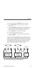
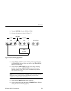
To test a circuit in the independently ground-referenced mode,
follow these steps:
1. Turn the POWER off to the PS280 or PS283.
2. Connect the outputs as shown in Figure 5.
3. Set both variable supply VOLTAGE controls to the minimum
setting.