


SPRAA56
26 DSP/BIOS Real-Time Analysis (RTA) and Debugging Applied to a Video Application
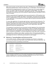
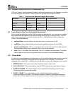
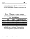
The value of N, which is used by modes 2 and 3, is 30 frames by default. As a result, RTA data
is logged every 1 second in NTSC applications. This value can be changed using the
GEL
→
rtaWindow slider. This slider asks for a value between 1 and 10 seconds, and multiplies
the value by 30 before updating the control variable in the application. For PAL applications,
change the multiplier value in the GEL file to 25.
5.4.2 Capture and Display Task Benchmarking
In addition to the RTA modes, you can enable or disable instrumentation in the capture and
display tasks using the USER0 and USER1 bits in the RTA Control Panel. They are turned on
by default. In order to view the latency from the input to output task, it is necessary to turn these
bits on. After a typical latency measurement is recorded, the amount of data the capture and
display tasks deliver to the Message Log may be more than is useful.
6 References
• H.263 Loopback on the DM642 EVM (SPRA933)
• The TMS320DM642 Video Port Mini-Driver (SPRA918)
• Reference Frameworks for eXpressDSP Software: RF5, An Extensive, High-Density
System (SPRA795)
• Reference Frameworks for eXpressDSP Software: API Reference (SPRA147)
• TMS320 DSP/BIOS User's Guide (SPRU423)
• TMS320C6000 DSP/BIOS API Reference Guide (SPRU403)
• DSP/BIOS TextConf User's Guide (SPRU007)
• DSP/BIOS Driver Developer's Guide (SPRU616)