


SPRAA56
DSP/BIOS Real-Time Analysis (RTA) and Debugging Applied to a Video Application 7
2.2 Requirements for Viewing RTA Benchmarks
In order for any of the DSP/BIOS-based RTA tools to be visible, the DSP/BIOS components in
Code Composer Studio version 2.30 or earlier and version 3.0 require that the application’s .cdb
configuration file be accessible and consistent with the executable .out file.
This requirement is easily met during development. It can also be satisfied in demonstrations or
delivered test examples. If you do not want to deliver source code with the application for
external testing or demonstration, you can still enable all the RTA tools by providing a current
DSP/BIOS configuration .cdb file along with the executable .out file to be tested. The tester will
be able to view the CPU load, individual thread statistics, and other important benchmark details
described in the sections to follow.
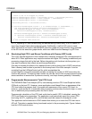
The RTA tools can be used in stop mode or real-time mode. In the GBL module of the
DSP/BIOS configuration, you can enable or disable real-time analysis. If you disable real-time
analysis, the three RTA functions in the IDL background loop are removed. Those functions
normally move RTA data from buffers on the DSP to the host PC and calculate the CPU load for
the load graph.
When RTA is disabled, the Message Log, Statistics View, Execution Graph, and other RTA
windows are updated only when the DSP is halted. An update displays the most recent contents
of their respective buffers. This “stop mode” of RTA offers a good compromise when some
visibility is required, but the additional code and background function calls are undesirable. Stop
mode can also occur if RTA is enabled but the CPU is so heavily loaded that it never runs the
IDL background loop long enough to provide real-time updates. In either case of stop-mode
operation, the CPU Load Graph is not updated. However, the programmatic method for CPU
load measurement discussed later in this application note provides a useful working alternative.
The next section describes structural modifications made to the application to make it more
suitable for benchmarking and further development.
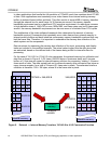
3 Modifications to the Base Example
The application associated with this document has very few structural changes from the base
application shipped with the TMS320DM642 evaluation module. Some variables have been
renamed for readability, the encoder and decoder have been separated, and an additional task
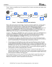
has been added for application control. The data flow in the application has not been modified.
The steps to convert the base example to the modified example are provided in a readme file in
the directory that contains the source code.
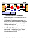
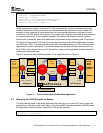
Figure 2 shows a more detailed look at the data flow in the modified H.263 loopback example: