


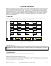
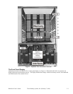
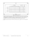

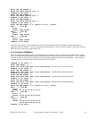

Figure 4 – RAM-SAN Front Panel
The RAM-SAN display consists of four rows of lights. Each row corresponds to one of the four RAM-SAN system busses.
The top row corresponds to interface ports 0, 1, 2 and 3, the next row to ports 4, 5, 6 and 7, the next row to ports 8, 9, 10 and
11, and the bottom row corresponds to interface ports 12, 13, 14, and 15. When any device on a bus is active, a light turns on
in the ADDRESSES section of the display corresponding to which gigabyte of memory it is accessing. Lights in the
BANDWIDTH section also turn on, showing the throughput of the bus in hundreds of megabytes per second.
The right-most section of the display shows which ports are loaded with devices. If a light is on, a device is present in that
slot.
RAM-SAN User’s Guide Texas Memory Systems, Inc. (February 7, 2003) 3-4