


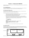

the memory connector – the connector has a key to keep the memory board from going in backwards or
awkwardly. Once in place, use the handles to evenly leverage the memory board into the slot.
• If none of the above hints helped, faulty hardware may exist. Follow the steps in section 6.4, Finding
Bad Memory, and try to pinpoint which memory board has a problem. Then contact Texas Memory
Systems customer support at (713)266-3200.
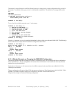
6.3.2 RAM-SAN Does Not Detect all Devices
When the boot sequence completes, all devices should be accounted for both in the READY lights on the front
panel display and on the status screen printed to the dumb terminal by the management port. If any devices
are missing, try the following. Please use a grounding strap and be careful around the power board – it is
dangerous.
• Verify that the system powered-up correctly by turning off the power for more than 30 seconds and then
turning it back on.
• Verify that all power modules have both the AC and DC LEDs on and the bad fuse LEDs off.
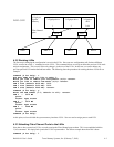
• If an interface is missing from the display, reseat the interface in the RAM-SAN. First, unscrew the
faceplate from the RAM-SAN. There are four screws that connect it to the chassis – one in each corner of
the front plate. Always turn off the power to the RAM-SAN before removing any boards from the
system. Pull the interface from the system using the handles. Examine the interface connector for
stress and wear. Examine the interface and check for loose components, particularly any socketed parts.
Use a flashlight to examine the interface port for stress and bent pins. Gently but firmly seat the
interface into its port using the slide rails as guides and tighten the faceplate screws.
6.3.3 Catastrophic Boot Error Detected
Call Texas Memory Systems for help diagnosing the problem.
6.4 Finding Bad Memory
This step-by-step guide will help you locate and confirm a faulty memory board or chip in your RAM-SAN. If
only a handful of bit errors are present, the problem may be with a single memory chip, which can be located
using this guide. If larger sections of the data word are affected, a more general board problem may exist.
See section 6 above for an example of where to look in the error message to see how many bits are at fault.
Please try to pinpoint the bad board and, if possible, chip, and then contact Texas Memory Systems customer
support.
6.4.1 Locating a Bad Memory Board
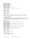
Bad memory will be reported by the system through an ECC error message. When data is read from
memory and the ECC value is incorrect, the device reports an ECC message to the management port. If the
error is a single bit error, the ECC logic corrects the data bit. Multiple bit errors are not correctable by the
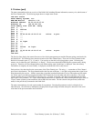
ECC mechanism. Use the ‘log’ command to display the following screen is an example of an ECC error log
report.
ram-san> log
Source: 0x0000, ECC word: 0x25, Burst addr: 0x0082000100, Error word cnt: 0x14
An error was detected on bit 9.
Bus: 2 Board: 4 Bank: 1
6.4.2 Confirming a Bad Memory Board
Once you have isolated the board and, if possible, the chip associated with an error, it is wise to double-check
that the problem is truly with the memory board, and not the system slot where the board resides. To test
this, turn off the power to the system, wait for the fans to stop, and swap the board in question with one of
the working memory boards. (Make sure to use a grounding strap when removing boards from the system.)
RAM-SAN User’s Guide Texas Memory Systems, Inc. (February 7, 2003) 6-6