


6.2.1 MCP21 Does Not Display Characters
If nothing is displayed on the dumb terminal connected to the RAM-SAN, try the following:
• Check for solid serial cable connection at both the management and the debug monitor.
• Be sure that the dumb terminal is set at 9600 baud, no parity, eight data bits, one stop bit, no flow control and US/CR
terminator.
• Try adding a null modem adapter to the serial connection.
6.2.2 Boot Sequence Does Not Complete
If the RAM-SAN hangs in the middle of its boot sequence, try the following:
• Verify that there is no RAM-SAN activity by viewing the bandwidth section of the front panel display (see section 3.6).
If there is activity, wait for it to complete.
6.2.3 Does Not Accept Character Input
If the RAM-SAN has booted successfully, but will not accept dumb terminal I/O, be sure that the ram-san> prompt is visible
and you should be able to type on the console. If character I/O does not work, try the following:
• Check for solid serial cable connection at both the RAM-SAN and at the dumb terminal.
• Make sure that the terminal is set at 9600 baud, no parity, eight data bits, one stop bit, no flow control and US/CR
terminator.
6.3 RAM-SAN Boots Incorrectly
During the power-up sequence of the RAM-SAN, the management port initializes and queries the system for configuration
information. During this time, minor internal diagnostics are run in the system. Most errors at this time will be one of three
things: the RAM-SAN detects no or partial memory; the RAM-SAN detects no or a few of the Fibre Channel ports; the
power-up sequence is interrupted by a catastrophic error such as a reset, internal trap, or SAMnet error.
6.3.1 RAM-SAN Detects Partial or No Memory
If the MCP21 reports on the boot screen that partial or no memory was detected, please do the following. Always use a
grounding strap and be careful around the power board – it is dangerous. Also, always turn off the power before moving any
boards in the system.
• If there is an interface in slot 8, remove it or move it to another slot. If there is a blank faceplate in slot 8, remove it.
Open the top lid of the RAM-SAN and then turn on the power.
• Verify that all power modules have both the AC and DC LEDs on and the bad fuse LEDs off.
• After all system activity has stopped and you see the VIM+ prompt displayed on the dumb terminal, verify that
none of the configuration LEDs are lit. These are the three right-most LEDs on the interface
motherboard. (See section 3.5) If any are lit, please consult section 6.7 for more information.
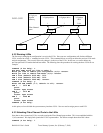
• Verify that your memory boards are in the correct memory slots. If you have two memory boards, they
should be in slots 0 and 4. If you have four memory boards, they should be in slots 0,1,4 and 5. If you
have six, they should be in slots 0,1,2,4,5 and 6. You must always have an even number of memory
boards in the system. See Figure 3 for a depiction of the RAM-SAN memory slots.
• Turn off the power and verify that all memory boards are tightly seated in the memory system. To do
this, press firmly on the memory board handles visible from the top of the system. The handles will
distribute pressure evenly on the memory board.
• Turn off the power and reseat the memory boards by lifting the handles from the memory board. Be
sure to wear a grounding strap attached to the RAM-SAN chassis – the RAM-SAN memory boards are
one of the most expensive parts of the system. The handles are designed to use the metal card cage as a
fulcrum to gently leverage out the memory boards. Once the memory board is removed, check its
connector for stress or damage. Use a flashlight to check the RAM-SAN memory board connectors for
damage. Seat the memory board back into the system by slowly sliding the memory board into the
memory slot using the card rails as a guide. Make sure the memory board handles are up so that they
hook underneath the card cage. Try to visually verify that the memory board has correctly seated into
RAM-SAN User’s Guide Texas Memory Systems, Inc. (February 7, 2003) 6-5