


Chapter 2 - Installation
The RAM-SAN is shipped with memory boards and interfaces already installed. Before connecting to a power supply, please
perform a preliminary inspection to check for any signs of loose parts, to ensure that all interfaces are still firmly positioned
in place, and to check for any obvious signs of damage. During power-up it is recommended that a terminal be attached to
the management port to observe its progress through the sequence of initial power-up tests. Once the system has completed
the power-up sequence, the management port should be used to execute a comprehensive system test prior to connection to
external devices, as detailed in section 2.6. See Chapter 4, Configuring the RAM-SAN, for more information on other
features of the management port.
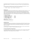
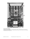
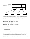
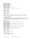
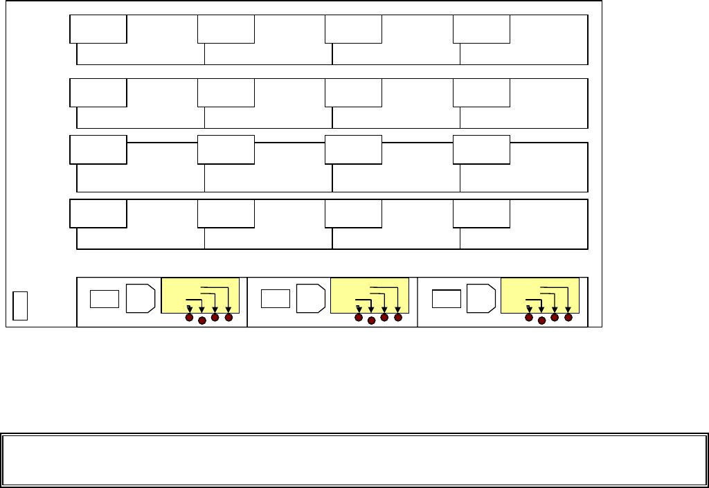
2.1 Inspection
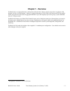
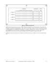
Inspect the rear of the chassis. Figure 1 shows the interface slot numbers for the RAM-SAN. Make sure that all of the
interfaces are securely installed in their slots, and that all screws are fully tightened.
RAM-SAN User’s Guide Texas Memory Systems, Inc. (February 7, 2003) 2-1
Slot 3
Slot 2
Slot 1
Slot 0
Slot 11
Slot 10
Slot 9
Slot 8
Slot 15
Slot 14
Slot 13
Slot 12
Slot 7
Slot 6
Slot 5
Slot 4
PWR-25
2A Fuse Bad
7A Fuse Bad
DC ON
AC ON
PWR-25
2A Fuse Bad
7A Fuse Bad
DC ON
AC ON
I
O
PWR-25
2A Fuse Bad
7A Fuse Bad
DC ON
AC ON
I
O
I
O
Slot 3
Slot 2
Slot 1
Slot 0
Slot 11
Slot 10
Slot 9
Slot 8
Slot 15
Slot 14
Slot 13
Slot 12
Slot 7
Slot 6
Slot 5
Slot 4
PWR-25
2A Fuse Bad
7A Fuse Bad
DC ON
AC ON
PWR-25
2A Fuse Bad
7A Fuse Bad
DC ON
AC ON
PWR-25
2A Fuse Bad
7A Fuse Bad
DC ON
AC ON
PWR-25
2A Fuse Bad
7A Fuse Bad
DC ON
AC ON
I
O
I
O
PWR-25
2A Fuse Bad
7A Fuse Bad
DC ON
AC ON
PWR-25
2A Fuse Bad
7A Fuse Bad
DC ON
AC ON
I
O
I
O
I
O
I
O
Figure 1 – Rear view of RAM-SAN
2.2 E.S.D. Warning
IMPORTANT: please take full E.S.D. precautions if it is necessary at any time to come into contact with any circuit boards,
components or connectors. The components used in the RAM-SAN and its interfaces are easily damaged by electrostatic
discharge.
2.3 Rack Mounting
The RAM-SAN comes complete with rack slides for mounting in a standard 19” rack.
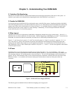
2.4 Connecting to the management port
The RAM-SAN is equipped with a management port that handles system initialization during power-up. The port can also be
used to execute system diagnostics, modify configuration, and monitor activity on the Fibre Channel ports. The management
port supports both Ethernet and serial connections.