


Chapter 3 - Understanding Your RAM-SAN
3.1 Interface Slot Numbering
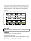
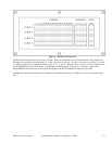
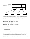
Each device in a RAM-SAN has a unique internal address based on the physical location of the device in the system. An
interface’s port number can be determined by inspecting the back of the RAM-SAN (see Figure 1).
3.2 Inside the RAM-SAN
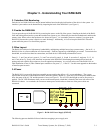
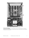
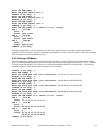
You can open the top of the RAM-SAN by removing the screws on the lid of the system. Standing at the back of the RAM-
SAN and looking down into the system the interfaces are closest to you, followed by the interface motherboard, and then the
memory slots. Please refer to the top-down view shown in Figure 3. As a reminder, please use caution if you open up the
RAM-SAN because the system is sensitive to static discharge. Additionally, it is best to keep the RAM-SAN lid on the
system while the power is on for airflow purposes.
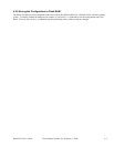
3.3 Bus Layout
The RAM-SAN achieves its high memory bandwidth by multiplexing multiple busses into system memory – four in all. A
RAM-SAN bus is a direct connection to or from memory. Each bus supports up to 800MBytes per second. To maximize bus
bandwidth, several devices share bus connections, and each device is individually arbitrated for bus use.
Ports 0, 1, 2, and 3 are on bus A, ports 4, 5, 6, and 7 are on bus B, ports 8, 9, 10 and 11 are on bus C, and ports 12, 13, 14,
and 15 are on bus D. If only a few interfaces are present in the RAM-SAN, distributing them among all four buses and
putting each active DMA device alone on a bus can optimize performance. As you look at the rear of the RAM-SAN, an
ideal installation of four (4) Fibre Channel ports would be to use ports 3, 7, 11 and 15. Use this same approach as the number
of interface ports increase.
3.4 Power
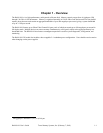
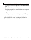
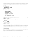
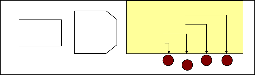
The RAM-SAN is powered by three hot-swappable power supplies that deliver a 2+1 power redundancy. The system
requires that at least two of the modules be active while the system is turned on. There are LEDs on the power modules that
show the status of the AC, DC and the protective fuses (see Figure 2). The AC LED should light as soon as line power is
applied. The DC LED illuminates when you turn on the master power switch that is located in the lower left corner of the
RAM-SAN chassis. As a reminder, do not turn on master power switch unless at least two of the power cables are
connected.
I
O
PWR-25
2A Fuse Bad
7A Fuse Bad
DC ON
AC ON
I
O
PWR-25
2A Fuse Bad
7A Fuse Bad
DC ON
AC ON
Figure 2 – RAM-SAN Power Supply (PWR-25)
The following process should be followed when hot-swapping a power supply unit:
RAM-SAN User’s Guide Texas Memory Systems, Inc. (February 7, 2003) 3-1