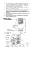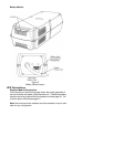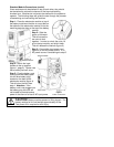
Operating the UPS
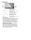
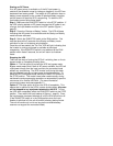
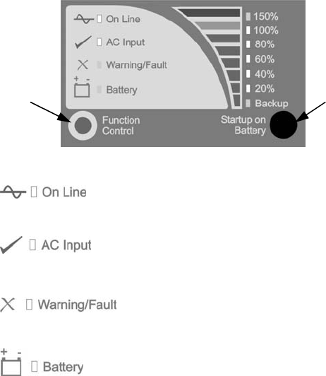
Display Panel Layout
ON LINE (green lamp)
Lights green when the UPS’s inverter is
supplying power to the load.
AC INPUT (green lamp)
Lights green when normal AC input power
is being supplied to the UPS unit.
WARNING/FAULT (red lamp)
Lights red when the UPS unit is
experiencing an abnormal condition.
BATTERY (red lamp)
Lights red to indicate that a condition exists
that is affecting the batteries.
Starting the UPS System
Once the modules have been connected as shown in the preceding
section (UPS Connections, page 10) the UPS system is ready to be
started. There are two ways to start the system: from AC input
power (if present) or from batteries. If not already done, switch the
input breaker on (figure 1, page 9). If the “AC Input” LED is lit,
proceed on to “Starting when AC power is available”. If the LED is
not lit, there is no AC power available. If the unit is to be started
when AC power is not available proceed to “Starting on DC power.”
Starting When AC Power is Available
If the system is being started with AC input power the system is
started by switching the RUN/STOP switch to the RUN position
(RUN = I, STOP = 0). When the RUN/STOP switch is in the RUN
position both the “AC Input” and the “On Line” LEDs should be lit.
When the unit is started with AC input power it is advisable to allow
time for the batteries to fully charge before any load is connected
(see “Battery Recharge Time”, page 16).
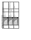
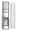
Startup on
Battery
Button
Function
Control
Button


