


Communication Interface
Dry Contacts
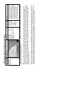
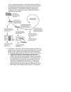
The remote contacts interface is a standard feature. It is provided
through solid state relays with contacts through a DB9 male
connector located on the back of the UPS (refer to the
Communication Option User Manual for a more detailed description
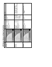
of this option). The following chart shows the signals and the
connector pinout.
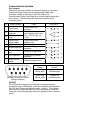
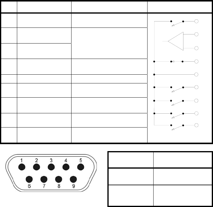
Pin Signal Function Logic In the UPS
1 Fault Signal
Closed when fault
detected
2
UPS stop
common
3
UPS stop signal
input
Backup stop when the
level changes from Low (-
3 to – 15V) to High (+3 –
+15V)
4
Normal input
power supply
Closed with normal
supply power
5 Signal common Common signal return
6 Bypass operation
Closed during bypass
operation
7
Battery voltage
low
Closed at voltage drop
8 UPS operation
Closed during inverter
operation
9
Power failure
signal
Closed at power failure
1
2
3
4
5
6
7
8
9
Voltage Current
48Vdc peak 100mAdc peak
30Vac rms
(42Vac peak)
70mAac rms
(100mAac peak)
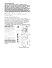
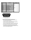
RS-232C
RS-232C serial communication interface is a standard feature
provided through a DB9 female connector located on the backside of
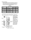
the UPS (see “Electronics Module Layout “, page 9). This interface
allows communication between the UPS and a personal computer.
The chart on the following page shows the signals and the connector
pinout.
DB9 Male Connector Outline
(facing connector)