


2. MAJOR UNIT REPLACEMENT EO18-33023
(Revision Date: Dec. 16, 2008)
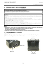
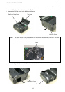
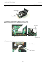
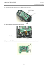
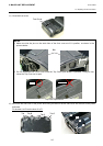
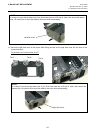
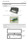
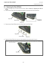
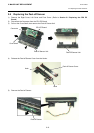
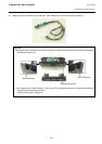
2.1 Replacing the CPU PC Board
2-7
NOTES:
1. After replacing the CPU PC Board, refer to the Setting Operation Manual or System Mode Manual an
d
perform the following operations.
1. Perform a RAM clear.
2. Perform the sensor adjustment.
2. After replacing the CPU PC Board, perform an LED check in the system mode and make sure the LED
lights properly. If the LED does not light properly, this may result from the disconnection of the
harness from the CPU PC board, the unset battery, or the run-down battery, etc. Make sure the
connection of the cables and the battery status. When they are correct, the LED failure may result
from the initial failure of the CPU PC board and replace the CPU PC board with a correct one.
Regarding the procedures for the LED check, refer to Section 4.2.3 in the System Mode Manual.