


2. MAJOR UNIT REPLACEMENT EO18-33023
(Revision Date: Dec. 16, 2008)
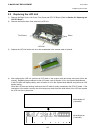
2.9 Replacing the Cover Open Switch and Media Sensor (Lower)
2-16
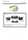
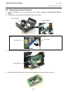
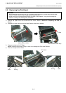
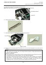
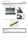
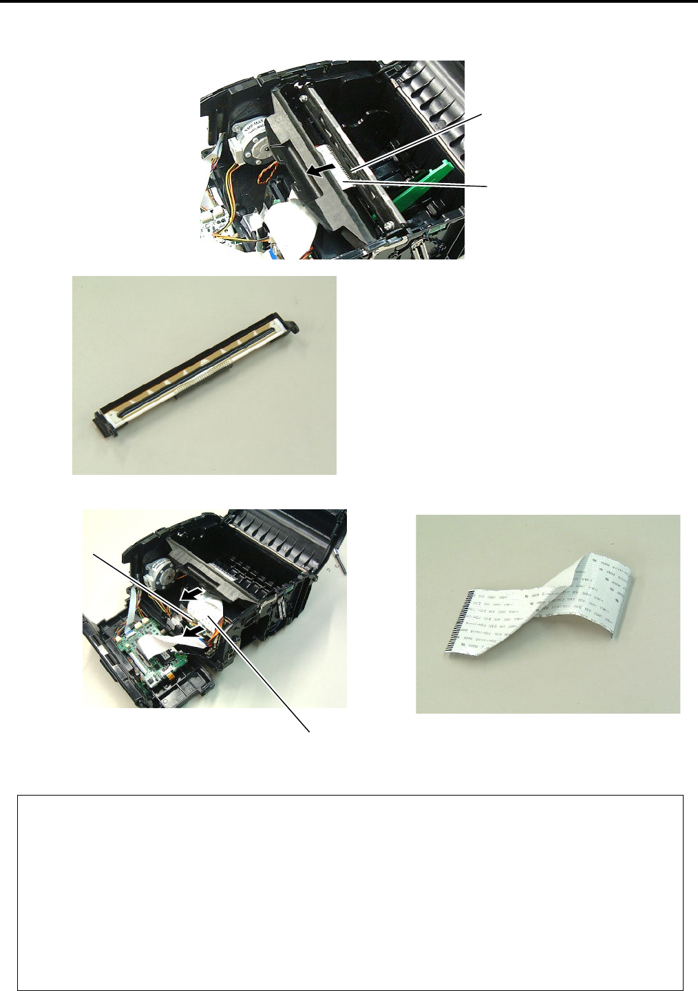
5) Disconnect the Head FPC from the Print Head Connector.
NOTE: When reassembling the Head FPC, the contact portion should be faced upward.
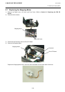
6) Remove the Print Head Ass’y.
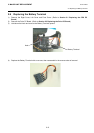
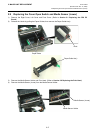
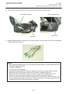
7) Disconnect the Head FPC Cable from the Drive PC Board Connector.
8) Replace the Print Head and Head FPC Cable with a new one, then reassemble in the reverse order of
removal.
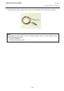
Head FPC Cable
Drive PC Board
Print Head Connector
Head FPC
NOTES:
1. After replacing the Print Head, refer to the Setting Operation Manual or System Mode Manual an
d
perform the following operations.
zPerform a RAM clear.
2. After replacing the Print Head, perform the print head broken element check and make sure none o
f
the elements are broken. (Refer to Section 4.2.2 in the System Mode Manual.)
Also perform a test print and make sure the print qualit
y
is correct. (Refer to Section 4.6 in the System
Mode Manual.) If the print tone is dark or light, perform the print tone fine adjustment. (Refer to
Section 4.5.4 in the System Mode Manual.) If the media is smudged, this may result from the
smudged print head. In the case, refer to the Owner’s Manual and clean the print head.