


27
11. Wiring
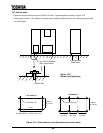
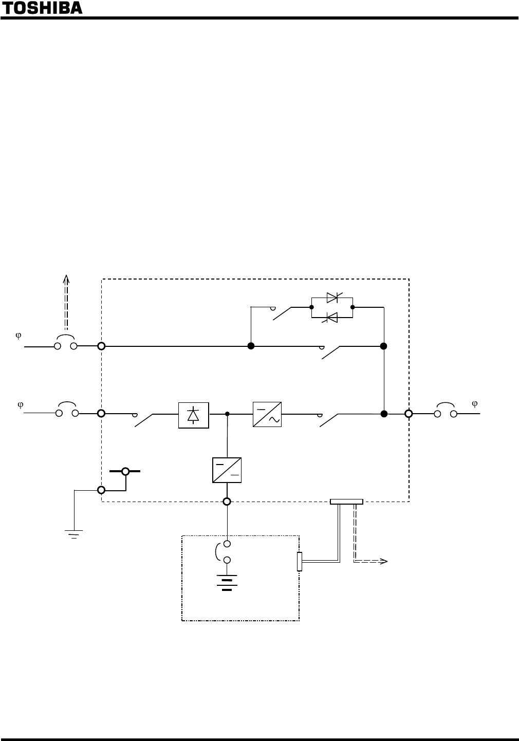
11.1 Overview
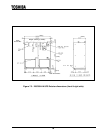
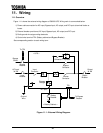
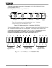
Figure 11.1 shows the external wiring diagram of G8000 UPS. Wiring work is summarized below.
1) Power cable connection for AC input, Bypass Input, AC output, and DC input at terminal blocks or
buses.
2) External breaker provision at AC input, Bypass Input, AC output, and DC input.
3) Earth ground wire at grounding electrode.
4) Control wire terminal TB1 (Battery cabinet and Bypass Breaker).
See corresponding section to each wiring term.
Figure 11.1 - External Wiring Diagram.
Battery
Breaker
< Battery Cabinet >
Bypass
Breaker
Bypass
3
4W
Input
Breaker
AC Input
3
3W
Output
Breaker
Output
3
4W
DC input
Bypass
Contactor
Contactor + Thyristor
Input
Contactor
Inverter
Contactor
Inverter
Chopper
Charger
Rectifier
< UPS >
TB1
Ground
Wire
To Bypass
Breaker
To TB1