


31
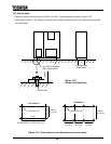
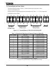
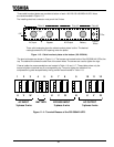
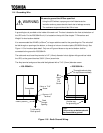
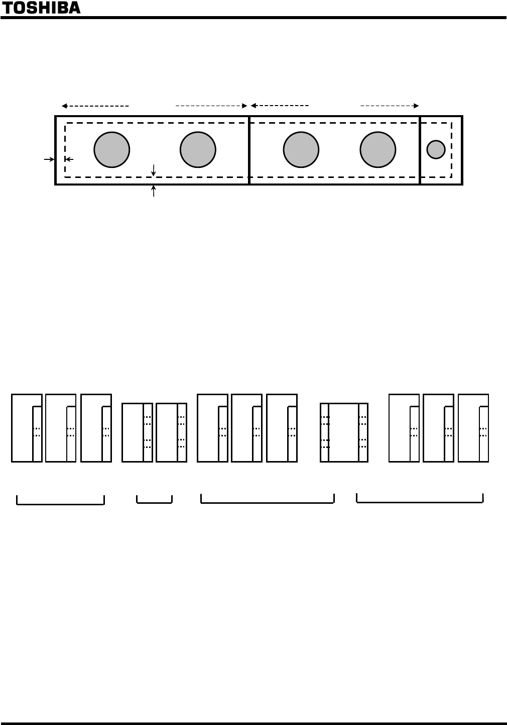
Three cable knockout plates are provided at bottom of each 100/125/150/180/225kVA UPS. Holes
are recommended in Figure 11.3.
The installing electrical contractor must punch the 5 holes.
Three solid rectangles show the cable knockout plates’ outline. The dashed
rectangle shows the UPS opening under the plates.
Figure 11.3 - Cable knockout plates at the bottom (100~225kVA).
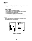
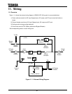
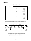
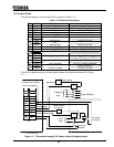
The terminal busses are shown in Figure 11.4. The busses are located inside of the 250/300kVA UPS at the
top. The dashed line shows the side view of the screw holes. The screws are used to tighten the lugs.
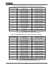
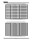
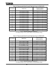
External cable size recommendations are located in Table 11.6 and 11.7. These tables show only the
torque to tighten a terminal bus & a corresponding lug. Torque to tighten the cable end in a
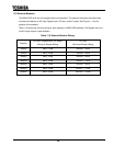
compression lug shall be specified by the lug vendor recommended in Table 11.8.
Figure 11.4 - Terminal Busses of the 250/300kVA UPS.
0.4”
0.8”
4” Dia.
2” Dia.
AC Input
Bypass
AC Output
Battery
Control
Wires
Plate #1
Plate #2
Plate #3
3-phase 3-wire
3-phase 4-wire
1 2 3 64 5 7 8 9 10 11 12
U V
W
- +
U V
W
VUN
W
AC INPUT
BYPASS INPUT
BATTERY
AC OUTPUT
3-phase 4-wire