


36
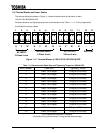
11.5 Control Wires
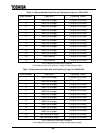
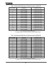
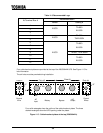
The terminal layout of control wires at TB1 is shown in Table 11.10.
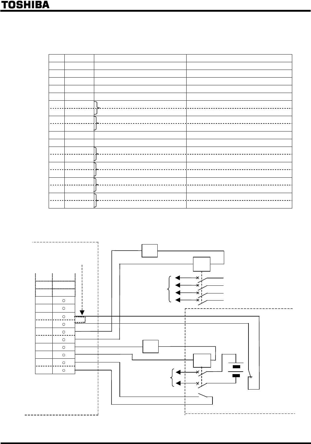
Table 11.10 External Connections
No. I/O Signal Name Operation
1 Output Low Battery Close at Low Battery
2 Output Backup Operation Close while Backup Operation
3 Output Fault Close by Faults
4 Output Inverter Supply Close during Normal Operation
5 Output Warning Close by Warnings
6 Input P24
7 Input Remote Run Close to run UPS
8 Input P24
9 Input Remote Stop Close to stop UPS
10 Output Bypass Supply Close during Bypass Operation
11 Output Output Signal Ground (Ground for pin #1~5 & #10)
12 Input P24 Battery’s
13 Input Battery Overheat Overheat B-contact
14 Output Bypass Breaker
15 Output 52C Trip Signal Shunt Trip Signal by EPO
16 Output Battery Breaker shunt trip
17 Output 72B Trip Signal by EPO or Battery shutdown
18 Output Battery breaker’s
19 Output 72B Aux. Contact Auxiliary A-contact
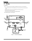
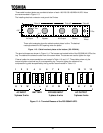
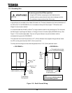
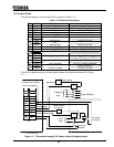
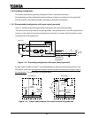
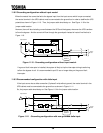
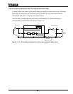
The UPS, the battery cabinet, and the bypass breaker should be wired as shown in Figure
11.7.
10
11
12
13
14
15
16
17
18
19
Figure 11.7 - Connection among UPS, battery cabinet & bypass breaker
To Bypass
Input
TC
< Battery Cabinet >
Overheat
B-contact
Power source
for trip coil
TB1
Auxiliary A-
contact
Jumper wire if battery
OH is not applied
.
TC
Power source
To DC
Input
Bypass Breaker
< UPS Cabinet >