


October 2000 © TOSHIBA TEC 5 - 1 MD-0101 CIRCUIT DESCRIPTION
5. CIRCUIT DESCRIPTION
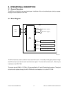
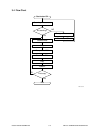
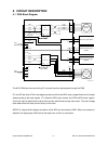
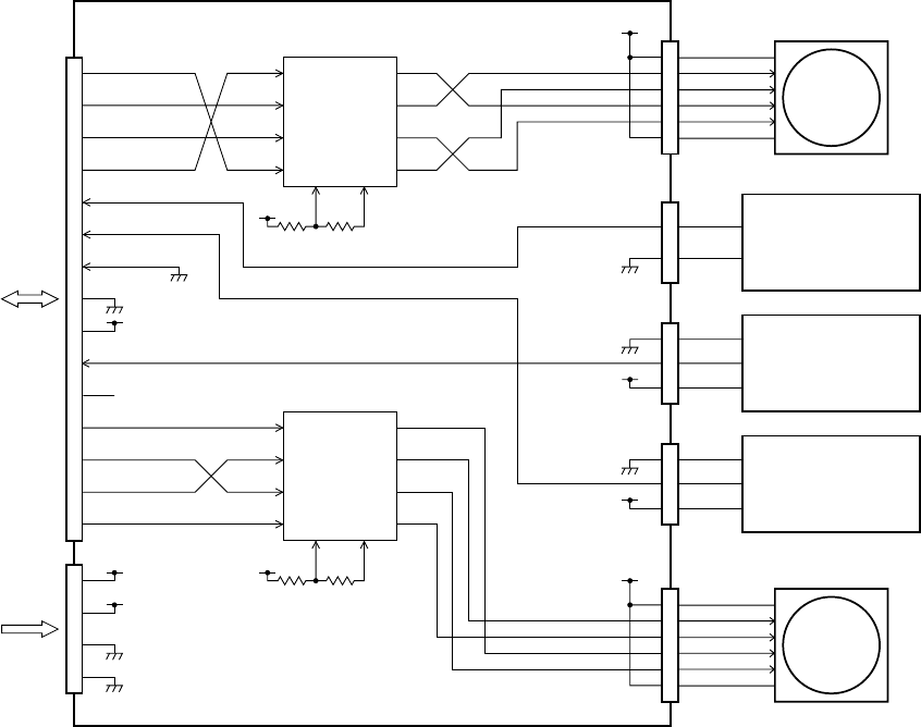
5.1 PWA Block Diagram
The ADU PWA has the motor driving IC only and the other signals pass through the PWA.
IC1 and IC2 are driver IC’s for the stepping motors and drive the ADU motors (upper/lower) on the output
side according to the input signals. IC1 drives the ADU motor (lower), and IC2 the ADU motor (upper).
Vref is the input to determine the value of the current which flows through each motor. The input voltage
there determines the load (current value) to the motor.
ADCNT is a signal which detects connection of the ADU and connected to GND. When its connector is
attached, the signal goes LOW so that the copier can confirm its connection.
ADU 05-01-01
SG
+5V
SG
2
3
1
+5V
SG
2
5
3
1
2
1
CN211CN212
+24V
6
4
2
3
1
+24V
PG
SG
R6 R7,R8
2
+24V
1
+5V
+5V
2
1
5
SG
4
3
PG
4
FDM-B
FDM-D
ADUFL
NC
ADUFU
ADUCOVSW
ADCNT
15
14
8
9
6
FDMC
FDMA
FDMB
FDMD
EXMC
EXMA
EXMB
EXMD
ADU PWA
PFC
PWA
3
5
4
3
12
2
8
9
6
7
5
4
3
2
8
9
6
7
AB
A
BB
VREF
B
A0
A1
B0
B1
7
11
10
FDM-A
FDM-C
15
14
CN213 CN217CN214
CN216
PFC
PWA
EXM-C
IC2
Motor driver
EXM-A
EXM-D
EXM-B
AB
A
BB
B
A0
A1
B0
B1
IC1
Motor driver
11
SP
ADU paper jam sensor
(
Upper
)
ADU paper jam sensor
(
Lower
)
ADU cover open switch
ADU motor
(
Upper
)
ADU motor
(
Lower
)
5
+24V
6
4
2
3
1
CN215
R14 R15,R16
+5V
12
VREF
11
SP