


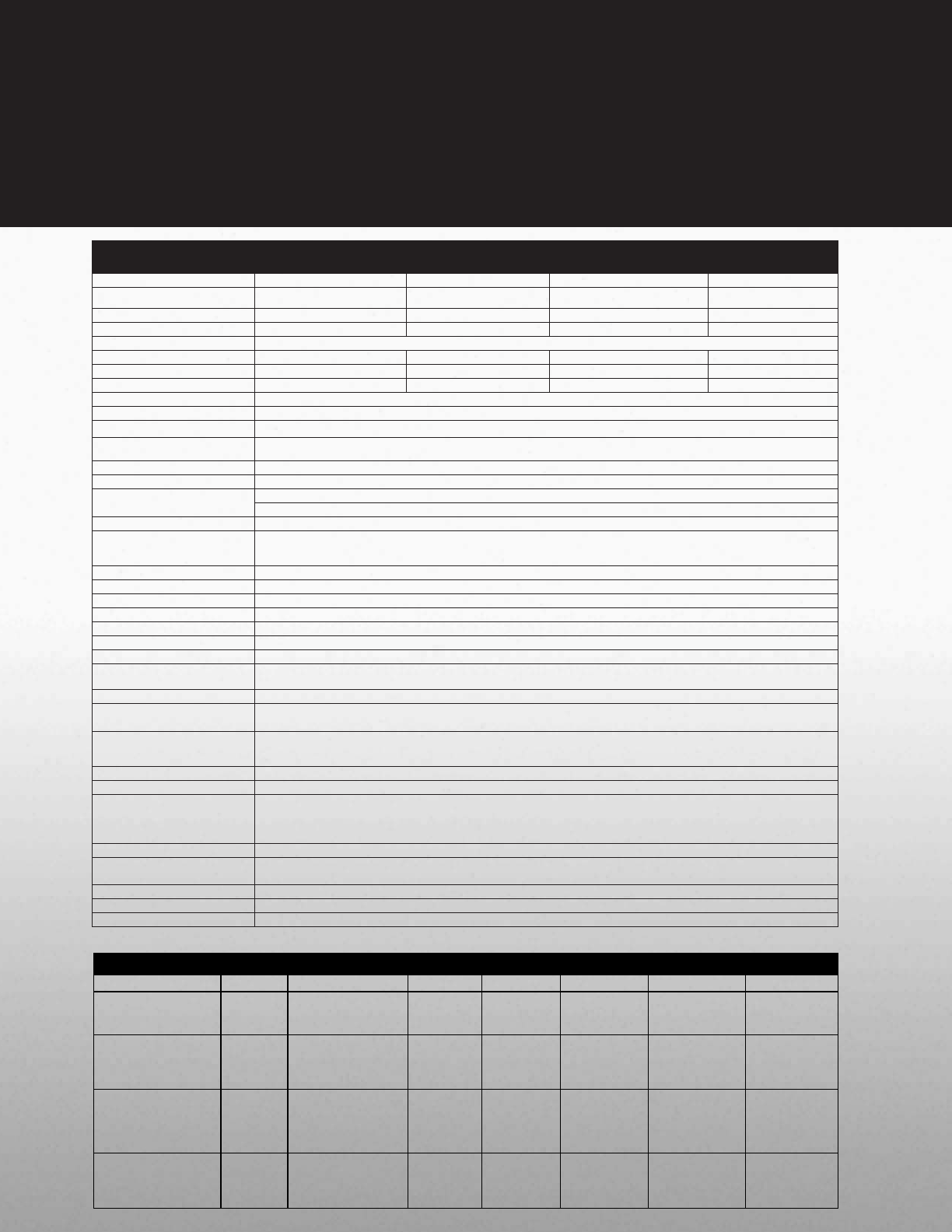
nC1 ASD Standard Specifications
Model Range 1001P-1007 P 2002P-2022P 2001PL-2022PL 2002P-2022P
Input Voltage Rating 120 V/Single Phase 230 V/Single Phase 230 V/Three Phase
230 V/Single Phase with
RFI / EMI Filter
KW Range 0.1 to 0.75 KW 0.2 to 2.2 KW 0.1 to 2.2 KW 0.2 to 2.2 KW
HP Range 1/8 to 1 HP 1/4 to 3 HP 1/8 to 3 HP 1/4 to 3 HP
Overload Rating 150% for 60 Seconds
Input Voltage Tolerance +10%, -15% +10%, -15% +10%, -15% +10%, -15%
Input Frequency Rating 50/60 Hz 50/60 Hz 50/60 Hz 50/60 Hz
Input Frequency Tolerance ± 5% ±5% ±5% ±5%
Output Voltage Rating 230 V, Three Phase
Color Munsel 5Y8 / 0.5
Control System Sinusoidal PWM Control
Output Voltage Range
Adjustable within a Range of 100 to 120% of Corrected Supply Voltage (200 V), Nonadjustable to any Voltage Higher than the Input
Voltage
Output Frequency Range 0.5 to 200 Hz, Default Setting: 0.5 to 80 Hz, Max Frequency: 30 to 200 Hz
Minimum Frequency Step 0.1 Hz: Operation Panel Setting, 0.2 Hz: Analog Input (when the Max Frequency is 100 Hz)
Frequency Accuracy
Digital Setting: within ±0.5% of the Max Frequency (-10 to +50°C)
Analog Setting: within ±1.0% of the Max Frequency (25°C ± 10°C )
V/f Characteristics V/f, Slip Frequency Compensation, Base Frequency, Base Frequency Voltage and Torque Boost (Adjustable Amount)
Frequency Setting Signal
Internal Pot on the Front Panel, External Frequency Signal (Connectable to a Volume with a Rated Impedance of 3 to 10 kΩ),
VI Terminal (Input Impedance: 42 kΩ (Voltage: 0 to 10 Vdc) or 250 Ω (Current: 4 to 20 mAdc)). Frequency can be Set Arbitrarily
Using a Two Point Setting
Startup & Jump Frequency Adjustable within a Range of 0.5 to 10 Hz; Up to 1 Frequency can be Adjusted Together with its Widths
PWM Carrier Frequency Selectable from among 2, 4, 8, 12, and 16 kHz (Standard Default Setting: 12 kHz or 4 kHz for Models with a Built-In EMI Noise Filter)
Accel/Decel Time Two Selectable Accel/Decel Times Adjustable from 0.1 to 3000 seconds
Retry Operation Selectable Number of Retries (Maximum 10 Times); If Protection Function is activated, Retry Function restarts after a main circuit check.
Electric Control Charging of Capacitor (Deceleration Time can be Shortened by Activating Forced Shortened Deceleration Mode)
Dynamic Braking Braking Start Frequency: 0 to Max Frequency; Braking Rate: 0 to 100%; Braking Time: 0 to 20 seconds
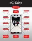
Input Terminal Functions Forward/Reverse Run Input Signal, Jog Run Input Signal, Standby Signal, Preset-Speed Operation Input Signal, Reset Input Signal, etc.
Output Terminal Functions
Frequency Lower Limit Output Signal, Frequency Upper Limit Output Signal, Low-Speed Detection Output Signal, Specified Speed
Attainment Output Signal, etc., Open Collector, RY Output
Failure Detection Signal 1 Form C Contact, Rated: 250 Vac, 2A, cosØ = 0.4
FM/AM Output
PWM Output: (1 mAdc Full-Scale DC Ammeter or 7.5 Vdc Full-Scale DC Ammeter/Rectifier-Type AC Voltmeter, 225% Current Max
1 mAdc, 7.5 Vdc Full-Scale)
Protective Function
Stall Prevention, Current Limitation, Overcurrent, Output Short Circuit, Overvoltage, Overvoltage Limitation, Undervoltage, Ground Fault,
Power Supply Phase Failure, Output Phase Failure Overload Protection by Electronic Thermal Function, Armature Overload at Startup,
Load-Side Overtorque at Startup, Overheating Prevention, Detection of Analog Signal Break
Momentary Power Failure Protection Auto-Restart Control after Momentary Power Failure
Electronic Thermal Characteristics Switching between Standard Motor/Constant- Torque VF Motor, Overload Trip, Overload Stall Selection
4-Digit, 7-Segment LED
Frequency: Inverter Output Frequency
Alarm: Stall Alarm “C,” Overvoltage Alarm “P,” Overload Alarm “L,” Overheat Alarm “H.”
Status: Inverter Status (Frequency, Cause of Activation of Protective Function, Input / Output Voltage, Output Current, etc.) and Parameter
Settings
Free-Unit Display: Arbitrary Unit (e.g. Rotating Speed) Corresponding to Output Frequency
Indicator Lamps Indicate Inverter Status by Lighting, such as RUN Lamp and PROGRAM Lamp
Use Environments
Indoor-Altitude: 1000 Meters (Maximum), not Exposed to Direct Sunlight, Corrosive Gas, Explosive Gas or Vibration (Less than 5.9 m
2
)
(10 to 55 Hz)
Ambient Temperature -10 to +50˚C
Storage Temperature -20 to +65˚C
Relative Humidity 20 to 93% Non-Condensing
Standard Specifications
nC1 ASD Standard Specifications
Model Range
1001P-1007P
2002P-2022P
2001PL-2022PL
2002P-2022P
Input Voltage Rating
120 V / Single Phase
230 V / Single Phase
230 V / Three Phase
230 V / Single Phase with
RFI / EMI Filter
KW Range
0.1 - 0.75 KW
0.2 - 2.2 KW
0.1 - 2.2 KW
0.2 - 2.2 KW
HP Range
1/8 - 1 HP
1/4 - 3 HP
1/8 - 3 HP
1/4 - 3 HP
Overload Rating
150% for 60 seconds
Input Voltage Tolerance
+10%, -15%
+10%, -15%
+10%, -15%
+10%, -15%
Input Frequency Rating
50 / 60 Hz
50 / 60 Hz
50 / 60 Hz
50 / 60 Hz
Input Frequency Tolerance
± 5%
±5%
±5%
±5%
Output Voltage Rating
230 V, Three Phase
Color
Munsel 5Y8 / 0.5
Control System
Sinusoidal PWM Control
Output Voltage Range
Adjustable within a range of 100 to 120% of the corrected supply voltage (200 V), nonadjustable to any voltage higher than the input voltage
Output Frequency Range
0.5 - 200 Hz, Default Setting: 0.5 - 80 Hz, Max Frequency: 30 - 200 Hz
Minimum Frequency Step
0.1 Hz: Operation Panel Setting, 0.2 Hz: Analog Input (when the Max Frequency is 100 Hz)
Digital Setting: within ±0.5% of the Max Frequency (-10 to +50°C)
Frequency Accuracy
Analog Setting: within ±1.0% of the Max Frequency (25°C ± 10°C )
V/f Characteristics
V/f, Slip Frequency Compensation, Base Frequency, Base Frequency Voltage and Torque Boost (adjustable amount)
Frequency Setting Signal
Internal Pot on the Front Panel, External Frequency Signal (connectable to a volume with a rated impedance of 3 -10 kΩ), VI Terminal (Input Impedance: 42 kΩ
(Voltage: 0 - 10 Vdc) or 250Ω (Current: 4 - 20 mAdc)). The frequency can be set arbitrarily using a two point setting.
Start-up & Jump Frequency
Adjustable within a range of 0.5 - 10 Hz, up to 1 frequency can be adjusted together with its widths
PWM Carrier Frequency
Selectable from among 2, 4, 8, 12 and 16 kHz (Standard Default Setting: 12 kHz or 4 kHz for models with a Built-In EMI Noise Filter)
Accel / Decel Time
Two selectable Accel / Decel Times adjustable from 0.1 to 3000 seconds
Retry Operation
Selectable number of retries (maximum 10 times); If the protection function is activated, the retry function restarts on completion of a check of the main circuit.
Electric Control
Charging of Capacitor (Deceleration Time can be shortened by activating Forced Shortened Deceleration mode.)
Dynamic Braking
Braking Start Frequency: 0 to Max Frequency, Braking Rate: 0 to 100%, Braking Time: 0 to 20 seconds
Input Terminal Functions
Forward / Reverse Run Input Signal, Jog Run Input Signal, Standby Signal, Preset-Speed Operation Input Signal, Reset Input Signal, etc.
Output Terminal Functions
Frequency Lower Limit Output Signal, Frequency Upper Limit Output Signal, Low-Speed Detection Output Signal, Specified Speed Attainment Output Signal, etc.,
Open Collector, RY Output
Failure Detection Signal
1 Form C contact, Rated: 250 Vac, 2A, cosØ = 0.4
FM / AM Output
PWM Output: (1 mAdc full-scale DC ammeter or 7.5 Vdc full-scale DC ammeter / Rectifier-type AC Voltmeter, 225% Current Max 1 mAdc, 7.5 Vdc full-scale)
Protective Function
Stall Prevention, Current Limitation, Overcurrent, Output Short Circuit, Overvoltage, Overvoltage Limitation, Undervoltage, Ground Fault, Power Supply Phase
Failure, Output Phase Failure Overload Protection by Electronic Thermal Function, Armature Overload at Start-up, Load-Side Overtorque at Start-up, Overheating
Prevention, Detection of Analog Signal Break
Momentary Power Failure Protection
Auto-Restart Control after momentary power failure
Electronic Thermal Characteristics
Switching between Standard Motor / Constant- Torque VF Motor, Overload Trip, Overload Stall Selection
Frequency: Inverter Output Frequency
Alarm: Stall Alarm "C," Overvoltage Alarm "P," Overload Alarm "L," Overheat Alarm "H."
Status: Inverter Status (Frequency, Cause of Activation of Protective Function, Input / Output Voltage, Output Current, etc.) and Parameter Settings
4-Digit, 7-Segment LED
Free-Unit Display: Arbitrary Unit (e.g. Rotating Speed) Corresponding to Output Frequency
Indicator
Lamps indicating the inverter status by lighting, such as RUN lamp and PRG lamp
Use Environments
Indoor- Altitude: 1000 m (maximum), not exposed to direct sunlight, corrosive gas, explosive gas or vibration (less than 5.9m
2
) (10 to 55 Hz)
Ambient Temperature
-10 to +50˚C
Storage Temperature
-20 to +65˚C
Relative Humidity
20 to 93% Non-Condensing
Model FLA & Approximate Dimensions (Inches) & Weight (Lbs)
VOLTAGE HP MODEL NUMBER FLA HEIGHT WIDTH DEPTH WEIGHT
0.12 VFNC1S-1001P 0.7 5.6 2.8 3.9 2.2
0.25 VFNC1S-1002P 1.4 5.6 2.8 3.9 2.2
0.5 VFNC1S-1004P 2.4 5.6 2.8 3.9 2.2
110 V
Single Phase
1.0 VFNC1S-1007P 4.0 5.6 4.6 4.9 2.2
0.25 VFNC1S-2002P 1.4 5.6 2.8 3.9 2.2
0.5 VFNC1S-2004P 2.4 5.6 2.8 4.9 2.2
1.0 VFNC1S-2007P 4.0 5.6 2.8 5.4 2.2
2.0 VFNC1S-2015P 7.5 5.6 4.6 6.1 3.3
230 V
Single Phase
3.0 VFNC1S-2022P 10 5.6 4.6 6.1 3.3
0.12 VFNC1-2001P 0.7 5.6 2.8 3.9 2.2
0.25 VFNC1-2002P 1.4 5.6 2.8 3.9 2.2
0.5 VFNC1-2004P 2.4 5.6 2.8 4.9 2.2
1.0 VFNC1-2007P 4.0 5.6 2.8 5.4 2.2
2.0 VFNC1-2015P 7.5 5.6 4.6 6.1 3.3
230 V
Three Phase
3.0 VFNC1-2022P 10 5.6 4.6 6.1 3.3
0.25 VFNC1S-2002PL 1.2 5.6 2.8 3.9 2.2
0.5 VFNC1S-2004PL 2.3 5.6 2.8 4.9 2.2
1.0 VFNC1S-2007PL 4.0 5.6 2.8 5.4 2.2
2.0 VFNC1S-2015PL 7.5 5.6 4.6 6.1 3.3
230 V
Single Phase
Built-in RFI / EMI Filter
3.0 VFNC1S-2022PL 10.7 5.6 4.6 6.1 3.3