


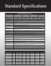
nC1 ASD Standard Specifications
Model Range 1001P-1007 P 2002P-2022P 2001PL-2022PL 2002P-2022P
Input Voltage Rating 120 V/Single Phase 230 V/Single Phase 230 V/Three Phase
230 V/Single Phase with
RFI / EMI Filter
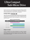
KW Range 0.1 to 0.75 KW 0.2 to 2.2 KW 0.1 to 2.2 KW 0.2 to 2.2 KW
HP Range 1/8 to 1 HP 1/4 to 3 HP 1/8 to 3 HP 1/4 to 3 HP
Overload Rating 150% for 60 Seconds
Input Voltage Tolerance +10%, -15% +10%, -15% +10%, -15% +10%, -15%
Input Frequency Rating 50/60 Hz 50/60 Hz 50/60 Hz 50/60 Hz
Input Frequency Tolerance ± 5% ±5% ±5% ±5%
Output Voltage Rating 230 V, Three Phase
Color Munsel 5Y8 / 0.5
Control System Sinusoidal PWM Control
Output Voltage Range
Adjustable within a Range of 100 to 120% of Corrected Supply Voltage (200 V), Nonadjustable to any Voltage Higher than the Input
Voltage
Output Frequency Range 0.5 to 200 Hz, Default Setting: 0.5 to 80 Hz, Max Frequency: 30 to 200 Hz
Minimum Frequency Step 0.1 Hz: Operation Panel Setting, 0.2 Hz: Analog Input (when the Max Frequency is 100 Hz)
Frequency Accuracy
Digital Setting: within ±0.5% of the Max Frequency (-10 to +50°C)
Analog Setting: within ±1.0% of the Max Frequency (25°C ± 10°C )
V/f Characteristics V/f, Slip Frequency Compensation, Base Frequency, Base Frequency Voltage and Torque Boost (Adjustable Amount)
Frequency Setting Signal
Internal Pot on the Front Panel, External Frequency Signal (Connectable to a Volume with a Rated Impedance of 3 to 10 kΩ),
VI Terminal (Input Impedance: 42 kΩ (Voltage: 0 to 10 Vdc) or 250 Ω (Current: 4 to 20 mAdc)). Frequency can be Set Arbitrarily
Using a Two Point Setting
Startup & Jump Frequency Adjustable within a Range of 0.5 to 10 Hz; Up to 1 Frequency can be Adjusted Together with its Widths
PWM Carrier Frequency Selectable from among 2, 4, 8, 12, and 16 kHz (Standard Default Setting: 12 kHz or 4 kHz for Models with a Built-In EMI Noise Filter)
Accel/Decel Time Two Selectable Accel/Decel Times Adjustable from 0.1 to 3000 seconds
Retry Operation Selectable Number of Retries (Maximum 10 Times); If Protection Function is activated, Retry Function restarts after a main circuit check.
Electric Control Charging of Capacitor (Deceleration Time can be Shortened by Activating Forced Shortened Deceleration Mode)
Dynamic Braking Braking Start Frequency: 0 to Max Frequency; Braking Rate: 0 to 100%; Braking Time: 0 to 20 seconds
Input Terminal Functions Forward/Reverse Run Input Signal, Jog Run Input Signal, Standby Signal, Preset-Speed Operation Input Signal, Reset Input Signal, etc.
Output Terminal Functions
Frequency Lower Limit Output Signal, Frequency Upper Limit Output Signal, Low-Speed Detection Output Signal, Specified Speed
Attainment Output Signal, etc., Open Collector, RY Output
Failure Detection Signal 1 Form C Contact, Rated: 250 Vac, 2A, cosØ = 0.4
FM/AM Output
PWM Output: (1 mAdc Full-Scale DC Ammeter or 7.5 Vdc Full-Scale DC Ammeter/Rectifier-Type AC Voltmeter, 225% Current Max
1 mAdc, 7.5 Vdc Full-Scale)
Protective Function
Stall Prevention, Current Limitation, Overcurrent, Output Short Circuit, Overvoltage, Overvoltage Limitation, Undervoltage, Ground Fault,
Power Supply Phase Failure, Output Phase Failure Overload Protection by Electronic Thermal Function, Armature Overload at Startup,
Load-Side Overtorque at Startup, Overheating Prevention, Detection of Analog Signal Break
Momentary Power Failure Protection Auto-Restart Control after Momentary Power Failure
Electronic Thermal Characteristics Switching between Standard Motor/Constant- Torque VF Motor, Overload Trip, Overload Stall Selection
4-Digit, 7-Segment LED
Frequency: Inverter Output Frequency
Alarm: Stall Alarm “C,” Overvoltage Alarm “P,” Overload Alarm “L,” Overheat Alarm “H.”
Status: Inverter Status (Frequency, Cause of Activation of Protective Function, Input / Output Voltage, Output Current, etc.) and Parameter
Settings
Free-Unit Display: Arbitrary Unit (e.g. Rotating Speed) Corresponding to Output Frequency
Indicator Lamps Indicate Inverter Status by Lighting, such as RUN Lamp and PROGRAM Lamp
Use Environments
Indoor-Altitude: 1000 Meters (Maximum), not Exposed to Direct Sunlight, Corrosive Gas, Explosive Gas or Vibration (Less than 5.9 m
2
)
(10 to 55 Hz)
Ambient Temperature -10 to +50˚C
Storage Temperature -20 to +65˚C
Relative Humidity 20 to 93% Non-Condensing
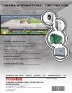
TOSHIBA — Quality by Design
Toshiba's culture and history are strongly rooted in quality. Our designs are
technologically innovative, and our products are manufactured from start to
end using only the highest quality domestic and foreign parts.
Product Warranty
Toshiba offers a comprehensive warranty program on its full line of industrial
products. Consult your salesperson or the factory for specific information.
Need to Know More?
Be sure to visit our website located at www.toshiba.com/ind for the latest
information on Toshiba products and services.
Customer Support Services
Toshiba offers 24-hour service nationwide. For assistance of any type
call: 1-800-231-1412.
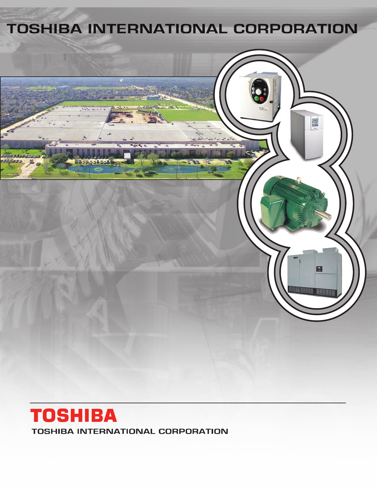
North America Headquarters & Manufacturing Facilities (Houston, TX)
Medium Voltage Motor
G7 Drive
ADJUSTABLE SPEED DRIVES MOTORS CONTROLS UPS INSTRUMENTATION PLC
INDUSTRIAL DIVISION
13131 West Little York Road, Houston, Texas 77041
Tel 713/466-0277 Fax 713/466-8773
US 800/231-1412 Canada 800/872-2192 Mexico 01/800/527-1204
www.toshiba.com/ind
Copyright 8/2007
Available Through:
*NC1brocct070815*