


[6] Handling Guide
102
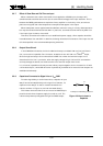
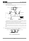
3.3.7 Effect of Slow Rise and Fall Time on Input
When a waveform with a slow rise and fall time is applied to a CMOS input, the output will
sometimes tend to oscillate around V
th
(the circuit threshold voltage) of the input waveform. This is
because the CMOS gate becomes an equivalent linear amplifier in the vicinity of V
th
, and minute
power source ripples and noise components are amplified and appear in the output.
When these power source ripples exceed the absolute maximum rating, it not only effects operation
but may also cause the device to break down. In particular, care must be taken while the power is on
if the input signal is slow to rise and fall.
Therefore, as mentioned in section 3.3.6, to stabilize the power supply, a filter capacitor should be
inserted between V
CC
and GND. In addition, the design should take into account of the input rise and
fall times specified in the recommended operating conditions.
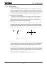
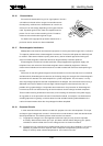
3.3.8 Output Short-Circuit
In the C
2
MOS
TM
ICs Series, a buffer is added to the output, and both flow-out (I
OH
) and flow-in
(I
OL
) current drive is possible. For this reason, excessive current will flow in a C
2
MOS
TM
output
when the high-level output line is shorted to the GND line or when the low-level output line is
shorted to the V
CC
line. In particular, when the supply voltage is high, IOH and IOL are excessive
and may damage the device; care must be taken not to cause an output short circuit.
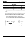
It is, of course, impossible to directly connect ordinary outputs together, but in the case of an IC with
a three-state output, a wired OR connection is permitted, provided that no more than two outputs are
enabled simultaneously.
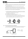
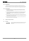
3.3.9 Capacitors Connected to Signal Line or V
CC
/GND
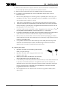
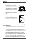
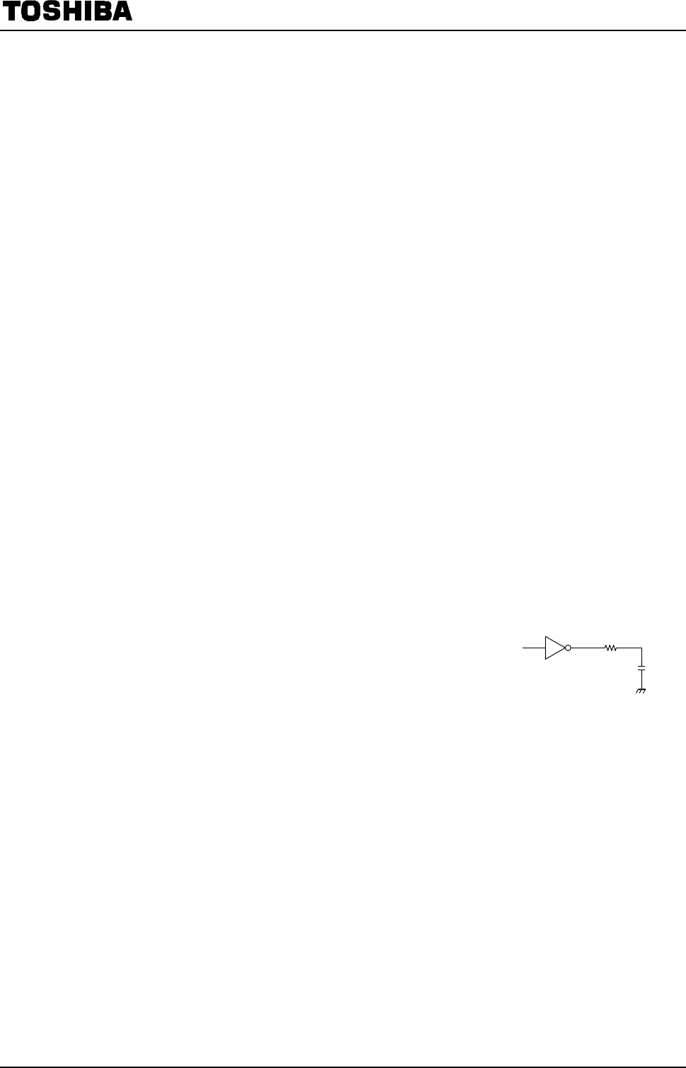
To reduce signal delay or to eliminate noise, a capacitor of up to
500 pF can be connected directly to the signal line. However, if a
capacitor of over 500 pF is used, it must be connected via a
resistor, as shown in Figure 3.3, and not connected directly .
This resistor limits the flow of the current to the CMOS output
parasitic circuit when the power supply is turned on or off. The
resistor also prevents prolonged shorting of the CMOS output.
Figure 3.3 How to Insert a
Capacitor
R
C
R: Output current-limiting resistance