


[6] Handling Guide
103
3.3.10 Wiring Precautions
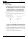
(1) Output waveform distortion
Since the output impedances of the Mini-MOS Series are very low, distortion is sometimes
caused in the output waveform by the L component of the wiring. This occurs when the wiring
connected to the output pin is long or when capacitance is connected between the signal line and
V
CC
or GND. Therefore, when designing a printed circuit board, take care not to make the signal
wiring too long. On the clock signal line, distortion of the waveform causes malfunctions.
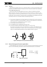
(2) Precautions for wiring arrangements
The outputs from the Mini-MOS Series have fast rise and fall times, and swing between V
CC
and GND; therefore they become a noise source to other signals. It is preferable to locate the
output away from components which are sensitive to noise from an analog circuit. Also, the
number of loads and the wiring length should be minimized.
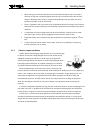
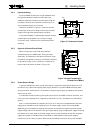
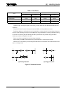
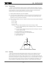
(3) Termination
Due to their physical and electrical characteristics, the Mini-MOS Series are apt to cause
overshoot and undershoot; this leads to malfunction of the circuit or the breakdown of passive
ICs. These problems can be prevented to some extent by terminating the signal line. Figure 3.4
shows examples of termination.
(a) Termination Using RC Components (b) Termination Using Diodes
Figure 3.4 Examples of Termination
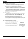
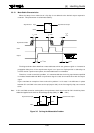
(4) Fan-out
In the case of a mutual interface between CMOS ICs, the input impedance of CMOS is so large
that there is little limitation on the number of fan-outs. However, there is a need to consider the
increase in propagation time due to the effect of adding load capacitance and the increase in
power consumption.
The input capacitance of CMOS is about 5 pF per input. If ten fan-outs are taken, for example,
the load capacitance is 50 pF. Additionally, the line capacitance of the printed circuit board must
be taken into account. This shows that the processing speed of the system is controlled not only
by the circuit components but also by the fan-out.
When designing a system using CMOS ICs, carefully consider the fan-out.