


TC9457F
2002-10-21
11
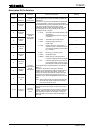
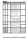
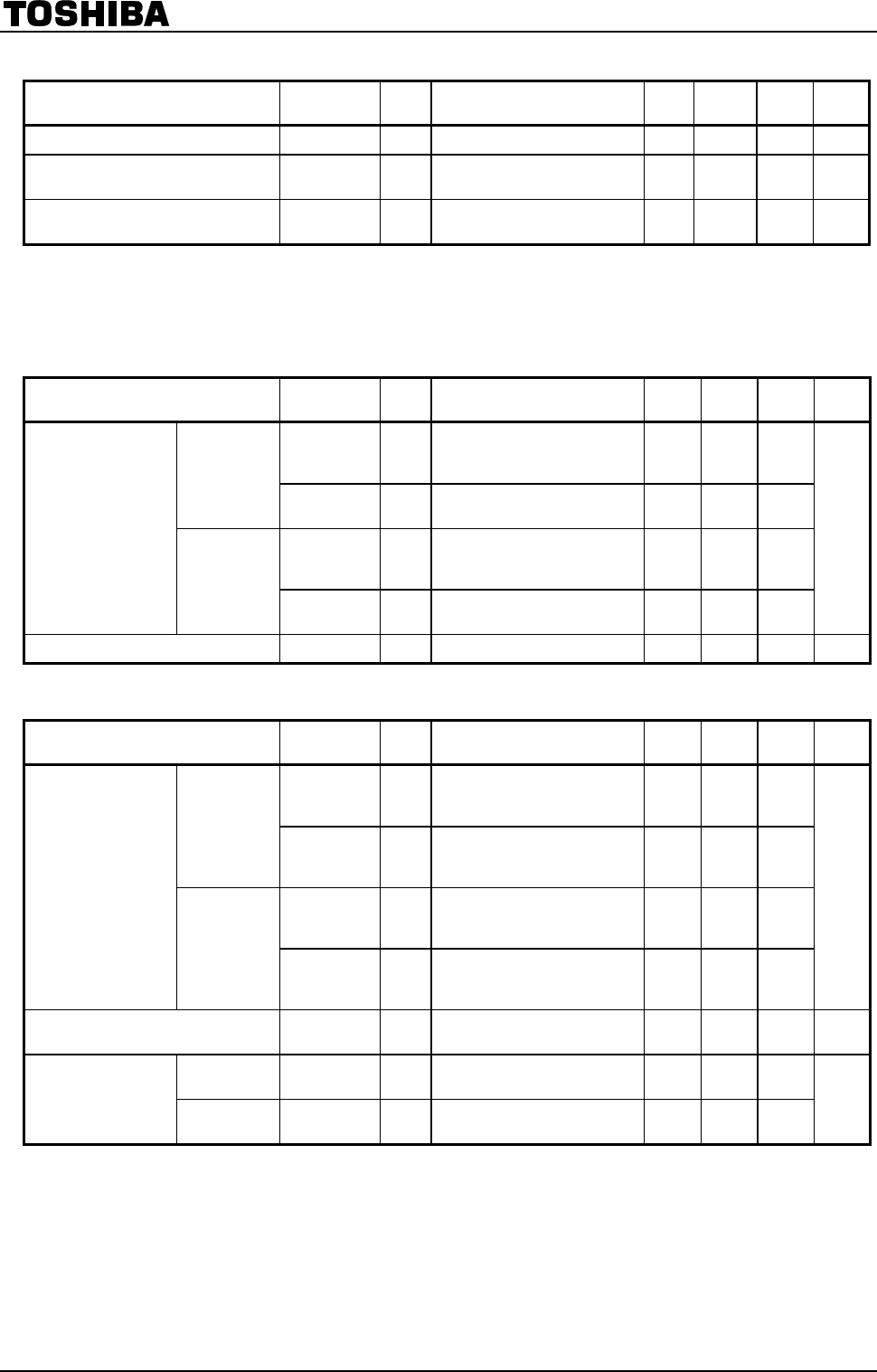
V
DD
(CD unit power supply)
Characteristics Symbol
Test
Circuit
Test Condition Min Typ. Max Unit
Operating supply voltage V
DD
― MV
DD
≥ V
DD
(Note 5) 4.5 5.0 5.5 V
Operating supply current I
DD
―
When 16.9344 MHz crystal
connected
― 50 60 mA
Crystal oscillation frequency f
XT
―
Rout = 0 Ω, Ci = Co = 15 pF
(Note 5, 6)
― 16.9344 ― MHz
Note 5: Guaranteed at V
DD
= MV
DD
= 4.5 to 5.5 V and Ta = −40 to 85°C
Note 6: Consider the crystal resonator used in your system when determining constants, etc.
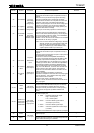
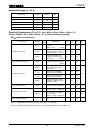
LCD Common Output
(COM1/OT1 to COM4/OT4)
Characteristics Symbol
Test
Circuit
Test Condition Min Typ. Max Unit
I
OH2
―
V
OH
= 4.5 V (When LCD
output, settings OT output,
LEDon = 0)
−0.1 −0.2 ―
High level
I
OH5
―
V
OH
= 4.5 V (Settings OT
output, LEDon = 1)
−20 −40 ―
I
OL2
―
V
OL
= 0.5 V (When LCD
output, settings OT output,
LEDon = 0)
0.1 0.2 ―
Output current
Low level
I
OL5
―
V
OL
= 0.5 V (Settings OT
output, LEDon = 1)
4 10 ―
mA
Output voltage 1/2 level V
BS
― Nonloaded (when LCD output) 2.1 2.3 2.5 V
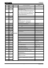
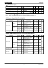
Segment Output
(S1/OT4 to S10/OT14, S11/OT15 to P8-0/S14 to P8-3/S18)
Characteristics Symbol
Test
Circuit
Test Condition Min Typ. Max Unit
I
OH1
―
V
OH
= 4.5 V
(When LCD output, settings
OT output, LEDon = 0)
−0.05 −0.1 ―
High level
I
OH4
―
V
OH
= 4.5 V
(Settings OT output,
LEDon = 1, I/O port)
−2 −4 ―
I
OL1
―
V
OL
= 0.5 V
(When LCD output, settings
OT output, LEDon = 0)
0.05 0.1 ―
Output current
Low level
I
OL5
―
V
OL
= 0.5 V
(Settings OT output,
LEDon = 1, I/O port)
5 10 ―
mA
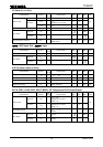
Input leakage current I
LI
―
V
IH
= 5.0 V, V
IL
= 0 V
(P8-0 to P8-3)
― ― ±1.0 µA
High level V
IH
― (P8-0 to P8-3)
MV
DD
× 0.8
~ MV
DD
Input voltage
Low level
V
IL
― (P8-0 to P8-3) 0 ~
MV
DD
× 0.2
V