


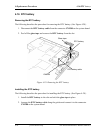
4.14 Cover assembly and Base assembly 4 Replacement Procedures
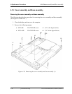
3. Turn over the computer and open the display.
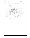
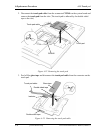
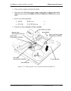
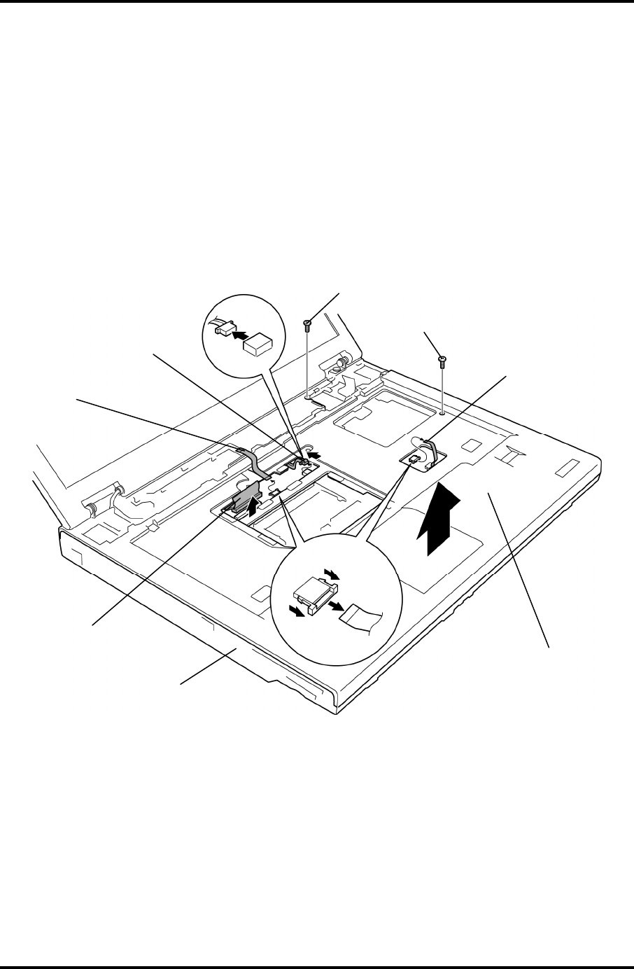
4. Disconnect the LCD cable, speaker cable, switch cable and finger print sensor
cable from the connector CN5000, CN6170, CN9500 and CN9550 on the system
board.
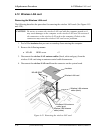
5. Remove the following screws.
• M2×4B BIND screw ×1
• M2.5×8B FLAT HEAD screw ×1
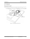
6. Separate the cover assembly and base assembly.
Base assembl
y
Cover assembl
y
M2×4B BIND
M2.5×8B FLAT HEAD
LCD cable
(Connected to CN5000)
Speaker cable
(Connected to CN6170)
Finger print sensor cable
(Connected to CN9550)
Switch cable
(Connected to CN9500)
Figure 4-25 Removing the cover assembly and base assembly (2)
TECRA M9 Maintenance Manual (960-631) [CONFIDENTIAL] 4-37