


70
Others
CONTENTS
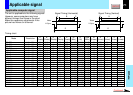
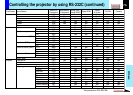
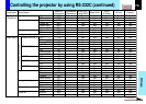
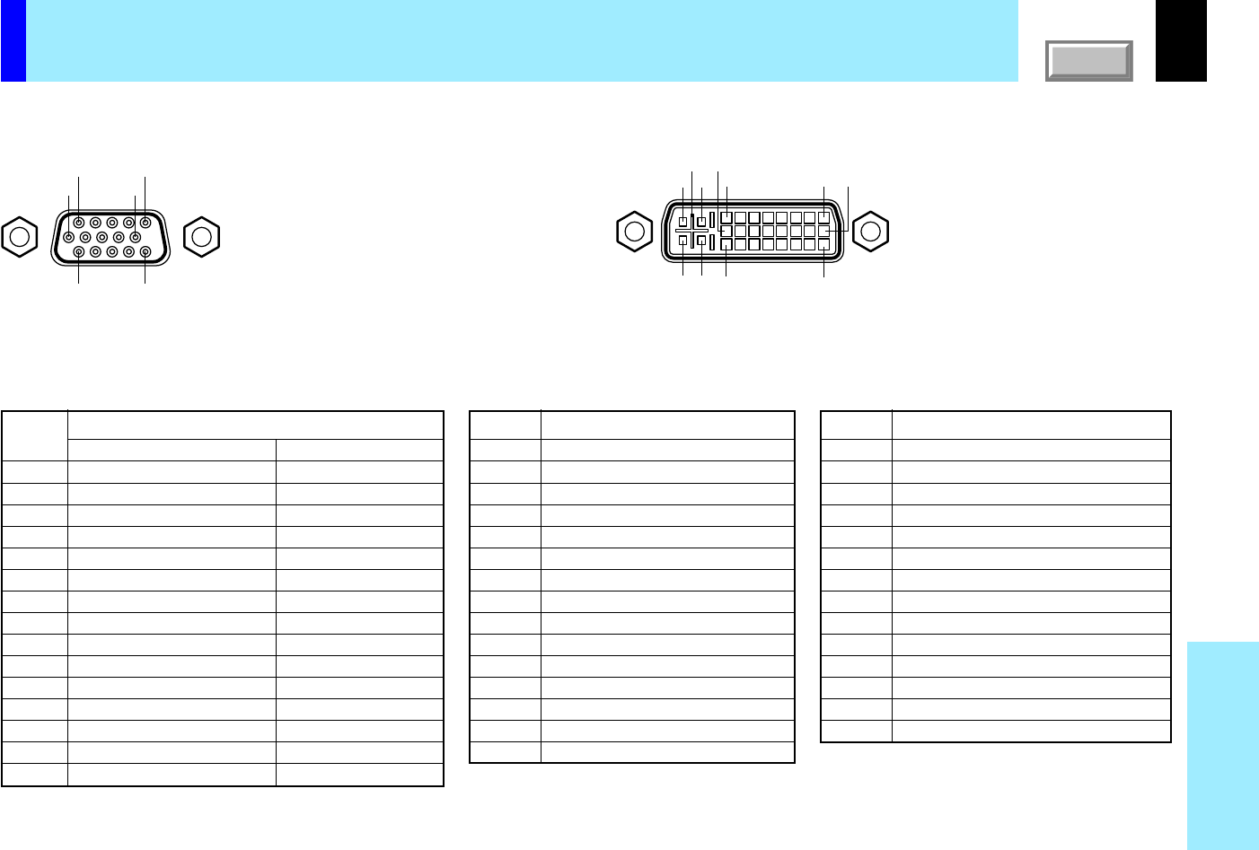
Mini D-sub 15pin
connector
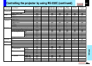
Pin No.
1
2
3
4
5
6
7
8
9
10
11
12
13
14
15
Description
T.M.D.S. data 2
-
T.M.D.S. data 2 +
T.M.D.S. data 2/4 shield
T.M.D.S. data 4
-
T.M.D.S. data 4 +
DDC clock
DDC data
Analog vertical sync signal
T.M.D.S. data 1
-
T.M.D.S. data 1 +
T.M.D.S. data 1/3 shield
T.M.D.S. data 3
-
T.M.D.S. data 3 +
+5V power
GND (+5V, H Sync & V Sync)
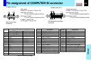
Pin assignment of COMPUTER IN connector
COMPUTER IN 1
COMPUTER IN 2
DVI ANALOG & DIGITAL
connector
Input signal
Analog R, G, B signal: 0.7V(p-p) 75Ω
Horizontal sync signal:
TTL level (positive/negative polarity)
Vertical sync signal:
TTL level (positive/negative polarity)
Y signal: 1.0V(p-p) 75Ω
PB, PR signal: 0.7V(p-p) 75Ω
Analog input signal
Analog R, G, B signal: 0.7V(p-p) 75Ω
Horizontal sync signal:
TTL level (positive/negative polarity)
Vertical sync signal:
TTL level (positive/negative polarity)
Pin No.
1
2
3
4
5
6
7
8
9
10
11
12
13
14
15
RGB input
Video signal (Red)
Video signal (Green)
Video signal (Blue)
GND
GND
GND (Red)
GND (Green)
GND (Blue)
N.C
GND
GND
DDC data
Horizontal sync signal
Vertical sync signal
DDC clock
Y/PB/PR input
Color difference signal (P
R
)
Luminance signal (Y)
Color difference signal (P
B
)
*
*
GND (PR)
GND (Y)
GND (PB)
*
*
*
*
*
*
*
Description
Pin No.
16
17
18
19
20
21
22
23
24
C1
C2
C3
C4
C5
Description
Hot plug detection
T.M.D.S. data 0
-
T.M.D.S. data 0 +
T.M.D.S. data 0/5 shield
T.M.D.S. data 5
-
T.M.D.S. data 5 +
T.M.D.S. clock shield
T.M.D.S. clock +
T.M.D.S. clock
-
Analog Video signal (Red)
Analog Video signal (Green)
Analog Video signal (Blue)
Analog horizontal sync signal
Analog GND (R,G & B)
*
: Do not connect anything.
51
10
1511
6
C5
C3 24C4
C1C2
8
1
16
17 9