


11
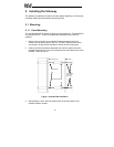
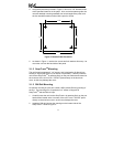
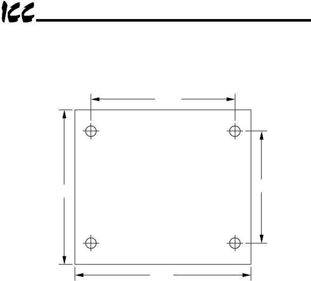
4. Using the dimensions provided in Figure 2, drill four 0.150” diameter holes
at the specified locations on the panel. As a convenient pattern guide, the
unit with attached mounting standoffs can be held against the panel, and
the four standoff locations marked with a pencil or scribe.
4.0 IN
3.5 IN
2.9 IN
4.0 IN
Figure 2: Standoff Hole Placement
5. As shown in Figure 1, use the four screws and lock washers from step 1 to
mount the unit from the back side of the panel.
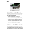
3.1.2 SnapTrack
TM
Mounting
The unit footprint measures 4” x 4” square, and is designed to fit directly into
existing 4” Augat SnapTrack
TM
(6TK series or equivalent). Carefully insert the
unit into the SnapTrack
TM
by pressing firmly on the pan head screws located at
the 4 corners of the unit’s cover. DO NOT press directly on the aluminum
cover, as this may damage the cover.
3.1.3 DIN Rail Mounting
An optional mounting kit (ICC part number 10581) allows DIN rail mounting of
the unit. The mounting kit is comprised of a 4” section of Augat 6TK
SnapTrack
TM
and two DIN rail clips.
1. Carefully insert the unit into the SnapTrack
TM
by pressing firmly on the pan
head screws located at the 4 corners of the unit’s cover. DO NOT press
directly on the aluminum cover, as this may damage the cover.
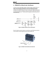
2. Install the DIN rail clips into the openings on the bottom side of the
SnapTrack
TM
. Refer to Figure 3.