


Configure Switch C:
Step Operation Description
1 Configure ports On VLAN→802.1Q VLAN page, configure the link
type of the related ports as Tagged, and add the ports
to VLAN101-VLAN106. The detailed instructions can
be found in the section 802.1Q VLAN
.
2 Enable STP function On Spanning Tree→STP Config→STP Config
page, enable STP function and select MSTP version.
On Spanning Tree→STP
Config→Port Config
page, enable MSTP function for the port.
3 Configure the region name and
the revision of MST region
On Spanning Tree→MSTP Instance→Region
Config page, configure the region as TP-LINK and
keep the default revision setting.
4 Configure VLAN-to-Instance
mapping table of the MST region
On Spanning Tree→MSTP Instance→Instance
Config page, configure VLAN-to-Instance mapping
table. Map VLAN101, 103 and 105 to Instance 1; map
VLAN102, 104 and 106 to Instance 2.
5 Configure switch C as the root
bridge of Instance 1
On Spanning Tree→MSTP Instance→Instance
Config page, configure the priority of Instance 1 to be
4096.
6 Configure switch C as the root
bridge of Instance 2
On Spanning Tree→MSTP Instance→Instance
Config page, configure the priority of Instance 2 to be
0.
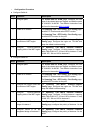
Configure Switch D:
Step Operation Description
1 Configure ports On VLAN→802.1Q VLAN page, configure the link
type of the related ports as Tagged, and add the ports
to VLAN101-VLAN106. The detailed instructions can
be found in the section 802.1Q VLAN
.
2 Enable STP function On Spanning Tree→STP Config→STP Config
page, enable STP function and select MSTP version.
On Spanning Tree→STP
Config→Port Config
page, enable MSTP function for the port.
3 Configure the region name and
the revision of MST region
On Spanning Tree→MSTP Instance→Region
Config page, configure the region as TP-LINK and
keep the default revision setting.
4 Configure VLAN-to-Instance
mapping table of the MST region
On Spanning Tree→MSTP Instance→Instance
Config page, configure VLAN-to-Instance mapping
table. Map VLAN101, 103 and 105 to Instance 1; map
VLAN102, 104 and 106 to Instance 2.
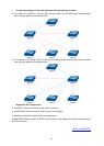
The configuration procedure for switch E and F is the same with that for switch D.
79