


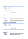

Individual:
Select this option to change the role of the switch to be individual
switch.
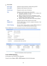
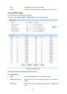
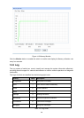
For an individual switch, the following page is displayed.
Figure 13-14 Cluster Configuration for Individual Switch
The following entries are displayed on this screen:
Current Role
Role: Displays the role the current switch plays in the cluster.
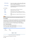
Role Change
Candidate: Select this option to change the role of the switch to be candidate
switch.
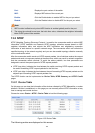
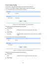
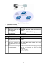
13.4 Application Example for Cluster Function
Network Requirements
Three switches form cluster, one commander switch(Here take TP-LINK TL-SL5428E as an
example) and two member switches(Here take TP-LINK TL-SL3428 as an example). The
administrator manages all the switches in the cluster via the commander switch.
Port 1 of the commander switch is connecting to the external network, port 2 is connecting to
member switch 1 and port 3 is connecting to member switch 2.
IP pool: 175.128.0.1, Mask: 255.255.255.0.
Network Diagram
194