


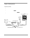


Configuration Changing IP Address
Trango Broadband Wireless — Atlas5010 page 18
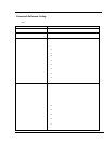
[Speed] 54 Mbps [Tx Power] 17 dBm [Power Range] -4..17 dBm
[Peer ID] DE1B7747 [Status] connected [RSSI] -44 dBm
[Peer IP Config] 10.8.2.139 255.255.255.224 10.8.2.129
Success.
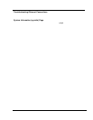
The [status] field indicates whether the MU and RU are connected or disconnected. If connected, the MU and RU will
automatically start passing Ethernet traffic over the wireless link.
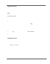
Changing IP Address
Use the ipconfig command to change the radio’s ip address, subnet mask and gateway.
Syntax: ipconfig [<ip> <subnet> <gateway>]
Example:
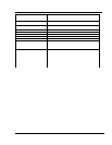
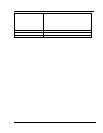
#> ipconfig 10.8.2.140 255.255.255.240 10.8.2.129
New configuration: [ip] 10.8.2.140 [subnet mask] 255.255.255.240 [gateway]
10.8.2.129
save and activate ? (y/n) [ATTN] Telnet session will be terminated in 30
seconds.
Success.
#>
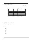
LEDs
LEDs are visible on the unit’s PCB between the reset button and the RJ-45 connector. The function of each
LED is described below:
LNK (green)
Green: On solid for an established 10BaseT or 100BaseT Ethernet Link.
SPEED
Green: Solid if 100BaseT, Blinks only if there is activity (TX or RX) on the network when a 100 MBit
connection is established. Off if a 10BaseT connection is established or if there is 10BaseT activity.
RSSI (4 LEDs)
Amber: Four LEDs
In all modes except “Survey”, the unit’s four yellow LEDs indicate the level of RF signal being
received from a VALID MU or RU as appropriate.
Yellow LED 1 : Begins blinking when RSSI is greater or equal to –90 dBm. On continuously at –85
dBm. This is the Leftmost LED
Yellow LED 2 : Begins blinking when RSSI is greater or equal to –80 dBm. On continuously at –75
dBm.
Yellow LED 3 : Begins blinking when RSSI is greater or equal to –70 dBm. On continuously at –65
dBm.
Yellow LED 4 : Begins blinking when RSSI is greater or equal to –60 dBm. On continuously at –55
dBm. This is the rightmost LED.
If no VALID MU or RU signal is detected the LEDs will not be on at all.