


Deployment & Installation
Trango Broadband Wireless — Atlas5010 page 27
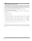
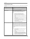
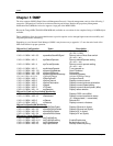
Ch 20 h 5755 : -82 / -96 n/a / n/a
Ch 20 v : -76 / -85 n/a / n/a
Ch 21 h 5775 : -97 / -98 n/a / n/a
Ch 21 v : -95 / -98 n/a / n/a
Ch 22 h 5795 : -75 / -81 n/a / n/a
Ch 22 v : -89 / -90 n/a / n/a
Ch 23 h 5815 : -90 / -91 n/a / n/a
Ch 23 v : -87 / -88 n/a / n/a
Ch 24 h 5835 : -78 / -79 n/a / n/a
Ch 24 v : -84 / -86 n/a / n/a
Success.
#>
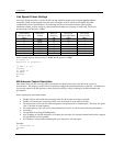
Channel Planning
Based on the results of the site survey at each end of the link, choose a channel which offers the lowest noise floor. In order to
reliably operate in the higher speed modes, clean spectrum is essential.
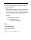
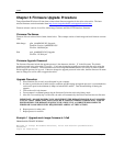
RSSI Command and Antenna Alignment
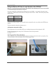
Once the site survey is completed, you are ready to install your radios. Typically it is best to install the MU first. To
properly align the radios, use the built-in RSSI tool to achieve maximum signal strength.
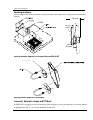
1. Ensure MU and RU are in Opmode “ON.”
2. Connect to the RU.
3. Login and type the command rssi. As you read the RSSI, move the antenna in
the horizontal and vertical planes until the maximum RSSI reading is achieved
4. If it is not possible to receive an adequate RSSI reading, it may be necessary to
reorient the MU (up/down, left/right), to increase the output power of the MU, or
to move the RU to a location with better line-of-sight conditions to the MU.
5. Once you are satisfied with the RSSI reading, tighten down the RU in the
optimum position.
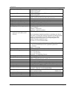
Example:
#> rssi
Press any key to stop.
0> MU -75 dB RU -75 dB Connected
1> MU -75 dB RU -75 dB Connected
2> MU -73 dB RU -73 dB Connected
3> MU -72 dB RU -71 dB Connected
4> MU -70 dB RU -70 dB Connected
5> MU -70 dB RU -69 dB Connected
6> MU -69 dB RU -70 dB Connected
7> MU -70 dB RU -70 dB Connected
8> MU -70 dB RU -70 dB Connected
9> MU -67 dB RU -68 dB Connected
10> MU -67 dB RU -67 dB Connected
Success.
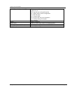
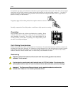
Users can also view the RSSI LEDs on the bottom of the radio. See the configuration section of this manual for more
information.