


Transition Networks SISPM1040-182D
Technical Support: 1-800-260-1312 International: 00-1-952-941-7600
Chapter 3 Hardware Installation
This chapter describes how to physically install the 8 10/100TX w/ X-Ring Managed
Industrial Switch.
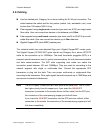
3.1 Installation Steps
1. Unpack the Industrial switch
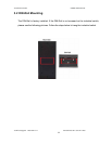
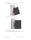
2. Check if the DIN-Rail is screwed on the Industrial switch or not. If the DIN-Rail is not
screwed on the Industrial switch, please refer to DIN-Rail Mounting section for DIN-
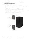
Rail installation. If users want to wall mount the Industrial switch, please refer to Wall
Mount Plate Mounting section for wall mount plate installation.
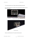
3. Hang the Industrial switch on the DIN-Rail track or wall.
4. Power on the Industrial switch. Please refer to the Wiring the Power Inputs section
for information about how to wire power. The power LED on the Industrial switch will
light up. Please refer to the LED Indicators section.
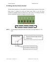
5. Prepare the twisted-pair, straight through Category 5 cable for Ethernet connection.
6. Insert one side of RJ-45 cable (category 5) into the Industrial switch Ethernet port
(RJ-45 port) and another side of RJ-45 cable (category 5) to the network device’s
Ethernet port (RJ-45 port), ex: Switch PC or Server. The UTP port (RJ-45) LED on
the Industrial switch will light up when the cable is connected with the network device.
Please refer to the LED Indicators section.
[NOTE]
Make sure that the connected network devices support MDI/MDI-X. If it does not
support, use the crossover category-5 cable.
7. When all connections are set and LED lights all show normal, the installation is
complete.