


6
SISTF10xx-140-LR(T) / -160-LR(T) / -170-LR(T)
24-hour Technical Support: 1-800-260-1312 -- International: 00-1-952-941-7600
Installation -- Continued
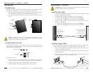
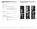
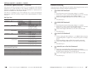
Set the Port Alarm Switches
The port alarm feature is used to determine faults at the copper or fiber ports.
The dip switches are located on the top panel of the device. Use a small flat
blade screwdriver or a similar device to set the switches.
SISTF10xx-140-LR(T)
• Switches 1 - 4 correspond to copper
ports 1 - 4, respectively.
• Switch 5 corresponds to fiber port 5.
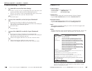
SISTF10xx-160-LR(T)
• Switches 1 - 6 correspond to copper
ports 1 - 6, respectively.
• Switches 7 and 8 correspond to fiber
ports 7 and 8, respectively.
SISTF10xx-170-LR(T)
• Switches 1 - 7 correspond to copper
ports 1 - 7, respectively.
• Switch 8 corresponds to fiber port 8.
on = Enables the corresponding port alarm. If the link for that port fails (or if
a power supply input fails), the internal relay forms an open circuit and
the FAULT LED lights up.
off = Disables the corresponding port alarm. The internal relay forms a
closed circuit and the FAULT LED remains off.
NOTE: To activate the updated switch setting, cycle the power to the
Ethernet switch by turning off the power, then turning it back on.
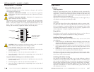
Internal Relay
The internal relay that activates the alarm feature is connected to the two
middle contacts on the 6-contact terminal block. A user-supplied fault alarm
device can be connected to these fault contacts. An example would be to
connect the fault circuit to a warning light located in the control room. The
light can be set up to turn on when a fault is detected. (See page 7.)
PORT
ALARM
DIP
OFF ON
ON
1
P1
2
P2
3
P3
4
P4
5
P5
SISTF10xx-140-LR(T)
PORT
ALARM
DIP
OFF ON
ON
1
P1
2
P2
3
P3
4
P4
5
P5
6
P6
7
P7
8
P8
SISTF10xx-160-LR(T)
SISTF10xx-170-LR(T)
Installation -- Continued
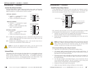
Install the Port Alarm Device
A user-supplied port alarm device can be connected to the Ethernet switch to
alert the user whenever a power fault or a port fault occurs. At least one port
alarm switch (see page 6) must be “ON” to enable the port alarm feature.
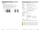
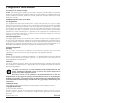
The contacts for the fault alarm are on the 6-contact terminal block, located
on the top panel of the Ethernet switch. To install a port alarm device:
1. Insert the two wires from the user-supplied port alarm device into the two
terminals marked “FAULT” on the 6-contact terminal block.
2. Secure the wire by tightening the corresponding screw on the side of the
terminal block.
techsupport@transition.com -- Click the “Transition Now” link for a live Web chat.
7
V2-
V1-
V1+
V2+
PWR2
FAULT
PWR1
V1, V2 INPUTS
12-48 VDC
The screws to secure
the wires are locate
d
on the side of the
terminal block.
fault contacts
6-contact terminal block
NOTE: Calculate the maximum possible current in each power wire and
signal wire. Observe all electrical codes for maximum current allowed.
If the current goes above the maximum ratings, the wiring would
overheat, causing serious damage to the network equipment.
Please note the following when wiring the network:
• Signal lines must not be directly connected to outdoor wiring.
• Use separate paths to route the power wiring and the signal wiring. If
power wiring and signal wiring paths must cross, make sure the wires are
perpendicular at the intersection point.
• Do not run signal wiring and power wiring in the same wire conduit. To
avoid interference, wires with different signal characteristics should also
be routed separately.
• Use the type of signal transmitted through a wire to determine which
wires should be kept separate. The rule of thumb is that wiring with
similar electrical characteristics can be bundled together.
• Keep input wiring and output wiring separate.
• Where necessary, label the wiring to all devices in the network.