


8
SISTF10xx-140-LR(T) / -160-LR(T) / -170-LR(T)
24-hour Technical Support: 1-800-260-1312 -- International: 00-1-952-941-7600
Installation -- Continued
Power the Ethernet switch
This device is suitable for use in Class I, Division 2, Groups A, B, C and D or
non-hazardous locations only.
WARNING: EXPLOSION HAZARD - Do not disconnect equipment
unless power has been removed or the area is known to be non-
hazardous.
WARNING: EXPLOSION HAZARD - Substitution of components may
impair suitability for Class I, Division 2.
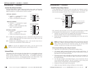
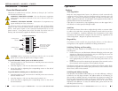
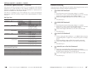
The Ethernet switch is designed for both a primary and a backup power
supply via the 6-contact terminal block, located on the top panel of the
device. Both power inputs can be connected simultaneously to live DC
power sources. If one power source fails, the other live source acts as a
backup, and automatically supplies the Ethernet switch with power.
CAUTION: Before connecting the Ethernet switch to the 12-48 VDC
power source, ensure the power source voltage is stable.
To provide PRIMARY (PWR1) power to the Ethernet switch:
1. Insert the positive (+) DC wire from the 12-48VDC power source into the
terminal marked “V1+”.
2. Insert the negative (-) DC wire into the terminal marked “V1-”.
3. Secure the wires by tightening the corresponding screws on the side of
the terminal block.
To provide BACKUP (PWR2) power to the Ethernet switch:
1. Insert the positive (+) DC wire from the 12-48VDC power source into the
terminal marked “V2+”.
2. Insert the negative (-) DC wire into the terminal marked “V2-”.
3. Secure the wires by tightening the corresponding screws on the side of
the terminal block.
V2-
V1-
V1+
V2+
PWR2
FAULT
PWR1
V1, V2 INPUTS
12-48 VDC
The screws to secure
the wire are located
on the side of the
terminal block.
backup power
contacts
p
rimary power
contacts
6-contact terminal block
techsupport@transition.com -- Click the “Transition Now” link for a live Web chat.
9
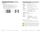
AutoCross
The AutoCross feature allows either straight-through (MDI) or crossover (MDI-
X) cables to be used when connecting the Ethernet switch to devices such as
PLCs or workstations. AutoCross determines the characteristics of the cable
connection and automatically configures the unit to link up, regardless of the
cable configuration. (Requires no operator intervention.)
Operation
Features
Auto-Negotiation
With the Auto-Negotiation feature, the Ethernet switch automatically
configures itself to achieve the best possible mode of operation over the
copper link. The device broadcasts its speed (10 Mb/s or 100 Mb/s) and
duplex capabilities (either full- or half-duplex) and negotiates the best mode of
operation between the two linked devices.
If the device is connected to a non-negotiating device over the copper link, it
will default to 10 Mb/s speed, half-duplex mode.
Plug-and-Play
The Ethernet switch models are plug-and-play devices, so that software
configuration is not required at installation or during maintenance.
Switching, Filtering, and Forwarding
Packets are either filtered or forwarded when they arrive at one of the
switched ports.
• Packets with source and destination addresses belonging to the same port
segment are filtered and constrained to one port (relieving the rest of the
network from the need to process them).
• Packets with a destination address to another port segment are forwarded
to the appropriate port, and are not sent to the other ports where it is not
needed.
• Packets that are used in maintaining the operation of the network (such as
the occasional multi-cast packet) are forwarded to all ports.
The Ethernet switch operates in the store-and-forward switching mode, which
eliminates bad packets and enables peak performance to be achieved when
there is heavy traffic on the network.
Switching and Address Learning
The Ethernet switch address table holds up to 1K node addresses, making it
suitable for use with large networks. The address tables are self-learning, so
that as nodes are added, removed, or moved from one segment to another, the
Ethernet switch automatically keeps up with new node locations. An address-
aging algorithm deletes the least-used addresses in favor of newer, more
frequently used addresses. To reset the address buffer, power down the unit
and then power it back up.