


10
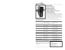
SISTF10xx-140-LR(T) / -160-LR(T) / -170-LR(T)
24-hour Technical Support: 1-800-260-1312 -- International: 00-1-952-941-7600
Operation -- Continued
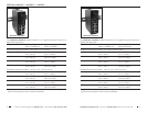
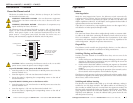
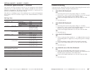
Status LEDs
Use the status LEDs to monitor the Ethernet switch operation in the network.
Power and Fault LEDs
The three LEDs near the top indicate the power and fault status:
PWR1 (amber) on = Primary power is connected to device.
PWR2 (amber) on = Backup power is connected to the device.
FAULT (red) on = If any of the five (5) port alarm switches are “on“
and the link on the corresponding port is inactive (ex:
switch 3 is “on” and port 3 is inactive); or there is a loss
of either the primary power or backup power.
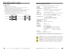
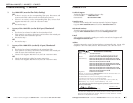
Fiber Port LEDs
The “100M” LEDs indicate the link status of the corresponding fiber port
(100Base-FX):
100M (green) on = Fiber link is active.
flashing = Data is being transmitted over the fiber link.
Copper Port LEDs
The LEDs embedded in each of the RJ-45 port indicate the status of the
corresponding copper link (10/100Base-T/TX):
10M (green) on = Copper link is active at 10 Mb/s.
flashing = Data is being transmitted over the copper link
at 10 Mb/s.
100M (green) on = Copper link is active at 100 Mb/s.
flashing = Data is being transmitted over the copper link
at 100 Mb/s.
Operation -- Continued
techsupport@transition.com -- Click the “Transition Now” link for a live Web chat.
11
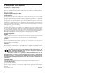
TX
PWR 1
PWR 2
FAULT
Industrial Switch
RX
10/100BASE-TX
100BASE-FX
100M
7
8
TX
TX
PWR 1
PWR 2
FAULT
Industrial Switch
RX
RX
100BASE-FX
100M
100M
5
6
TX
PWR 1
PWR 2
FAULT
Industrial Switch
RX
10/100BASE-TX
100BASE-FX
7
8
100M
5
6
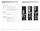
SISTF10xx-140-LR(T)
SISTF10xx-160-LR(T)
SISTF10xx-170-LR(T)