


16
SISTF10xx-140-LR(T) / -160-LR(T) / -170-LR(T)
24-hour Technical Support: 1-800-260-1312 -- International: 00-1-952-941-7600
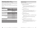
Test Description Test Levels
IEC 60068-2-6 Vibration 10 - 500 - 10 Hz, 0.5 oct./min, 4g, X, Y, Z (3 axes)
IEC 60068-2-27 Shock 50 g, 11 ms, +/-X, +/-Y, +/- Z (6 direction)
IEC 60068-2-32 Free fall 75 cm, 1 corner, 3 edges, 6 faces (total 10 drops)
Environmental Type Tests
Test Description Test Levels Severity
IEC61000-4-2 ESD Air discharge +/- 8 KV 3
Contact discharge +/- 6 KV 3
ESD contact discharge +/- 6 KV 3
IEC61000-4-3 Radiated RFI Housing 10V/m, 80 MHz - 1 GHz
AM 1 KHz, 80% mod
10 V/m, 0.9 - 1.8 GHz
FM 200 Hz 50% square
3
IEC61000-4-4 Burst
(Fast Transient)
Power supply lines +/- 2 KV 3
Communication lines +/- 1 KV 3
Relay +/- 1 KV 3
IEC61000-4-5 Surge Power supply lines +/- 2 KV, 12 Ω, CM
+/- 1 KV, 2 Ω, DM
3
Relay +/- 2 KV, 12 Ω, CM
+/- 1 KV, 2 Ω, DM
3
IEC61000-4-6 Induced
(Conducted RFI)
Power supply lines 10 Vrms, 150-80 MHz
AM 1 KHz, 80% mod
3
Communication lines 10 Vrms, 150-80 MHz
AM 1 KHz, 80% mod
3
Relay 10 Vrms, 150-80 MHz
AM 1 KHz, 80% mod
3
EMS Type Tests
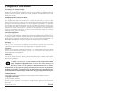
Technical Specification -- Continued
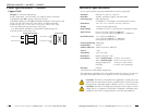
This device has been evaluated as EEx nC IIC T4 equipment under DEMKO
Certificate No. 03 ATEX 0324537U. Each module is suitable for use in Zone 2
Explosive Atmospheres. The device must be installed in a minimum IP 54
enclosure as defined in IEC 60529 and EN 60529.
This device is a building-in type. The installation into a certain end equipment
shall comply with fire enclosure request of IEC 60950/EN60950 or similar
sentence.
techsupport@transition.com -- Click the “Transition Now” link for a live Web chat.
17
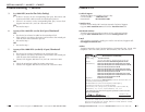
Troubleshooting
If the device fails, isolate and correct the fault by determining the answers to the
following questions and then taking the indicated action:
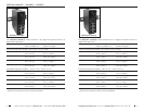
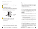
1. Is the PWR1 LED illuminated?
NO
• Ensure the power source is the proper voltage (12 - 48 VDC).
• Ensure the (+) and (-) wires from the power source are inserted
properly in the terminal block contacts labeled “PWR1”.
• Contact Tech Support: 800-260-1312, Int’l: 00-1-952-941-7600.
YES
• Proceed to step 2.
2. Is the PWR2 LED illuminated?
NO
• Ensure the power source is the proper voltage (12 - 48 VDC).
• Ensure the (+) and (-) wires from the power source are inserted
properly in the terminal block contacts labeled “PWR2”.
• Contact Tech Support: 800-260-1312, Int’l: 00-1-952-941-7600.
YES
• Proceed to step 3.
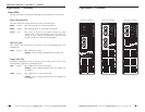
3. Is the FAULT LED illuminated?
YES
• If one or more port alarm switches (1 - 5) is ON, the device lost the
corresponding fiber or copper link, or the primary power or backup
power.
• Ensure the problem copper or fiber link is properly connected.
• Contact Tech Support: 800-260-1312, Int’l: 00-1-952-941-7600.
NO
• Proceed to step 4.
4. Is a 100M LED (near a fiber link) illuminated?
NO
• Check the corresponding fiber cables for proper connection.
• Verify that the TX and RX cables on the device are connected to the
RX and TX ports, respectively, on the other device.
• Contact Tech Support: 800-260-1312, Int’l: 00-1-952-941-7600.
YES
• Proceed to step 5.