13
IDENTIFYING EXTERNAL COMPONENTS
This chapter describes the front panel, rear panel, and LED indicators
of the Switch.
Front Panel
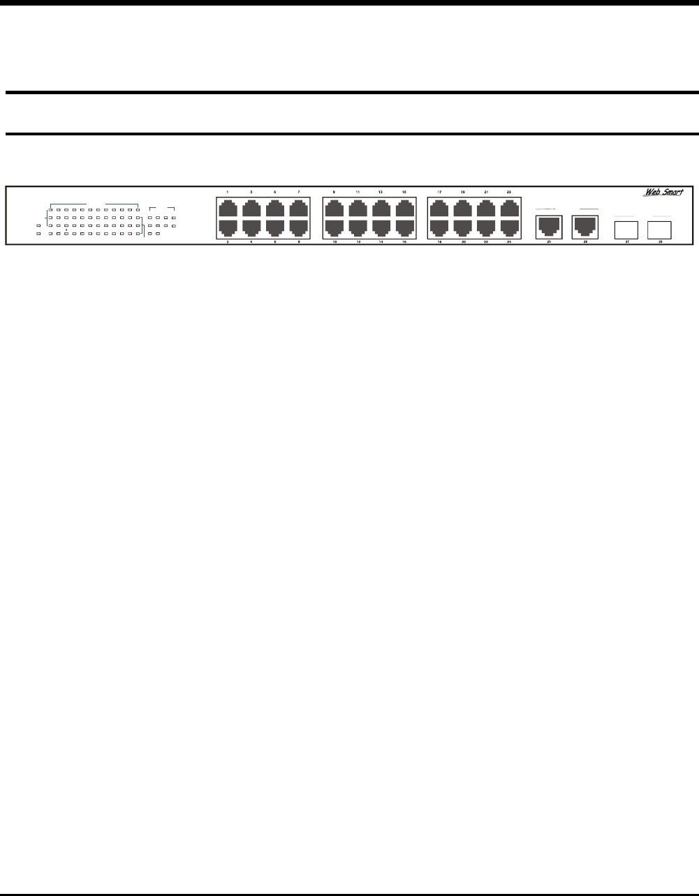
The figure below shows the front panels of the Switch.
28-Port 10/100/1000Mbps Web-SMART Gigabit Ethernet Switch
2
POWER
SYSTEM
4
810
12 14
16 18 20
22 24
13
5
7 9 11 13 15 17 19 21 23 25 26 27 28
Link/ACT
1000Mbps
100Mbps
10/100M
100Mbps
Link/ACT
Gigabit
1000BASE-T
Mini GBIC
Figure 3. Front panel of 24+4G-port Gigabit Ethernet Switch
LED Indicator:
Comprehensive LED indicators display the status of the switch and
the network (see the LED Indicators chapter below).
Fast Ethernet Ports (Port 1~24):
These ports support network speeds of either 10Mbps or 100Mbps,
and can operate in half- and full- duplex transfer modes. These ports
also supports automatic MDI/MDIX crossover detection function
gives true “plug and play” capability, just need to plug-in the network
cable to the hub directly and don’t care if the end node is NIC
(Network Interface Card) or switch and hub.
Gigabit Ethernet Ports (Port 25~26):
The Switch is equipped with two Gigabit twisted pair ports, supported auto
negotiable 10/100/1000Mbps and auto MDI/MDIX crossover detection
function. These two ports can operate in half-duplex mode for 10/100Mbps
and full- duplex mode for 10/100/1000Mbps.


