


SECTION 4 ADJUSTMENTS
4-- 1
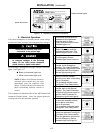
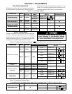
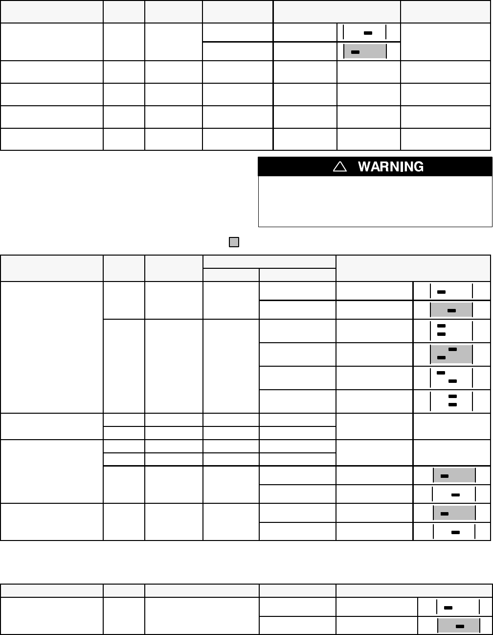
Time Delay Adjustment
Standard time delays are set to customer specifi cations
(if none specified, standard factory settings are used).
To change a setting, follow procedure on page 4-2. Use
Table 4-1 as a guide to time delay values and their corre-
sponding adjustment DIP switch or potentiometer.
Table4-1.TimeDelaySettings
DESCRIPTION LABELS
FACTORY
SETTING
ADJUSTMENT
RANGE
S3 DIP
SWITCH
ADJUSTMENT
POTENTIOMETER
Override Momentar
y
T
D
E
S
3
s
e
c
o
n
d
s
1second Actuator 1 on
1
O
v
e
r
r
i
d
e
M
o
m
e
n
t
a
r
y
Normal Source Outages
TD ES 3seconds
3seconds Actuator 1 off
1
—
T
r
a
n
s
f
e
r
t
o
E
m
e
r
g
e
n
c
y
TIMER 0 minutes 0to5
P
2
Transfer to Emergency
T
I
M
E
R
N
/
E
0
m
i
n
u
t
e
s
(full ccw)
0
t
o
5
minutes
—
—
P2
Override Momentary
Emergency S. Outages
— 4seconds non-adjustable — — —
R
e
t
r
a
n
s
f
e
r
t
o
N
o
r
m
a
l
TIMER 30 minutes 1secondto
P
1
Retransfer to Normal
T
I
M
E
R
E
/
N
3
0
m
i
n
u
t
e
s
(full cw)
1
s
e
c
o
n
d
t
o
30 minutes
—
—
P1
Unloaded Running
(Engine Cooldown)
— 5 minutes non-adjustable — — —
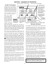
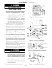
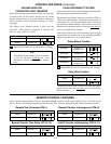
Sensor Adjustments
Voltage and frequency sensor pickup and dropout poi nts
are set to customer specifications (if none specified,
standard factory settings are used). To change a setting,
followprocedure on page4–2. Use Tables4-2 and 4–3for
settings and corresponding DIP switch actuators.
Any c hange in these s ettings may affect the
normal operation of the automatic transfer
switch. This change couldallow theload circuits
to remain connected to a low voltage source.
!
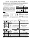
Ta ble 4-2. Voltage and Frequency Settings. ( Shaded DIP switches are standard factory settings).
D
E
S
C
R
I
P
T
I
O
N
L
A
B
E
L
S
S
E
T
T
I
N
G
%ofnominal
S1 DIP
DESCRIPTION LABELS SETTING
FACT . SET ADJ RANGE
S
1
D
I
P
SWITCH
P
U
/
N
P
i
c
k
u
p
9
0
%
95 % * Actuator 3 off
3
PU
/
N Pickup 90 %
90 % Actuator 3 on
3
90 % *
Actuator 1 off
Actuator 2 off
21
Normal Source Voltage
D
O
/
N
D
t
8
5
%
85 %
Actuator 1 on
Actuator 2 off
21
DO
/
N Dropout
85 %
80 %
Actuator 1 off
Actuator 2 on
21
70 %
Actuator 1 on
Actuator 2 on
21
Emer
g
enc
y
Source
–– Pickup 90 % non-adjustable
E
m
e
r
g
e
n
c
y
S
o
u
r
c
e
Voltage
–– Dropout 75 % non-adjustable
––
–– Pickup 95 % non-adjustable
E
S
–– Dropout 85 % non-adjustable
––
Emergency Source
Frequency
60
/
50
6
0
/
5
0
H
z
6
0
H
z
60 Hz Actuator 4 off
4
q
y
6
0
/
5
0
Hz
60
/
50 Hz 60 Hz
50 Hz Actuator 4 on
4
V
o
l
t
a
g
e
P
h
a
s
e
s
3
4
1
4
3
4
/
1
4
3
4
3phase Actuator 6 off
6
V
oltage Phases 3 4 ,14 3 4
/
1 4 3 4
1phase Actuator 6 on
6
* If dropout voltage is set to 90%, the pickup voltage must be set to 95%.
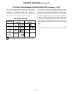
Table 4-3. Transformer Voltage Adjust.
(Low setting shifts all voltage settings down 4.2%; for example, 240 V to 230 V, or 480 V to 460 V)
DESCRIPTION LABELS FACTORY SETTING AD JUSTMENT S3 DIP SWITCH
V
o
l
t
a
g
e
A
d
j
u
s
t
(
4
2
%
)
LOW
/
H
I
LOW Actuator 2 off
2
V
oltage
A
djust (4.2%)
L
O
W
/
HI
HI
HI Actuator 2 on
2