


ADJUSTMENTS
(continued)
4-- 2
Do not make any setting changes
while the controller is energized.
!
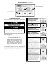
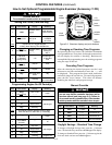
How to Change a Setting
1. Prevent thetransfer switch fromoperatingby discon-
necting one source first, then the other, as follows:
a. If the transfer switch is in the Normal position,
open the emergency source circuit breaker. Turn
the engine starting control to off. Then open the
normal source circuit breaker.
b. If the transfer switch is in the Emergency
position, opent he normalsource circuit breake r.
Turn engine starting control to test or run.Then
open the emergency source circuit breaker.
2. Disconnect both harness plugs from controller by
squeezing the latches. Do not pull on the wires.
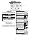
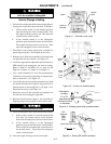
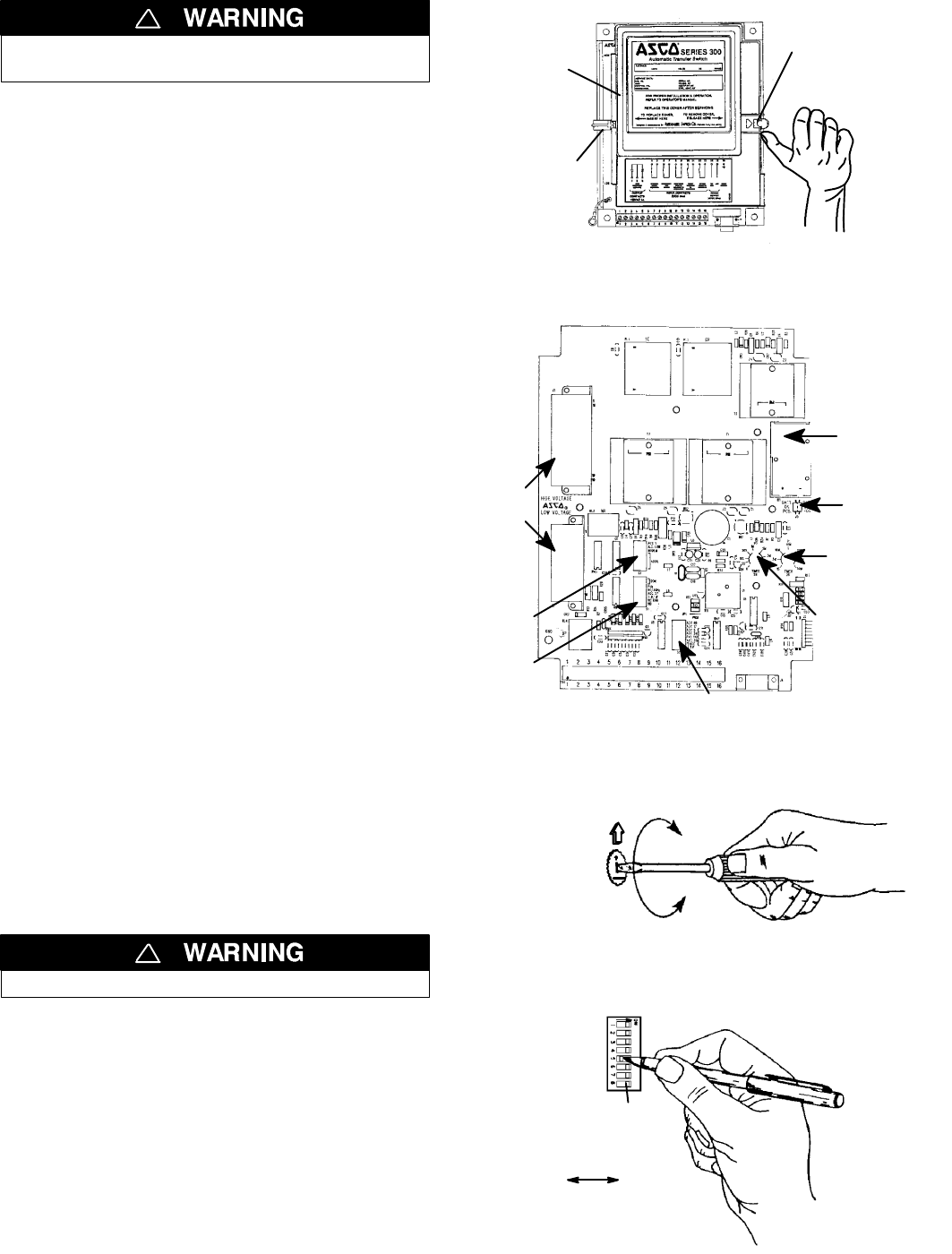
3. Remove cover from the controller by releasing latch
on right side with your thumb. See Figure 4-1.
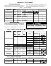
4. Locatetheappropriateadjustment potentiometeror
DIP switch for the setting that you want to change.
Refer to Table 4-1 and Table 4–2 on page 4-1 and
Figure 4-2, Figure 4–3, Figure 4–4 on page 4–2.
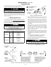
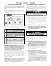
5. Use a small screwdriver to turn the potentiometer
clockwise to increase the time delay or counterclock-
wise to decrease it. See Figure 4-3.
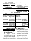
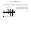
6. Use a ball-point pen (orsimilar pointed tool) to slide
the switch actuators left or right so they match the il-
lustration next to the setting (left = off, right = on).
Recheck the setting. See Figure 4-4.
7. Install the cover on the controller by hooking it on
the left side and latching the right side.
8. Reconnect both harness plugs to the controller by
aligning and pressing straight in until latches click.
Close the enclosure door.
!
9. Close the enclosure door, then restore both sources:
a. If the transfer switch is in the Normal position
first close the normal source circuit breaker,
then close the emergency source circuit breaker.
b. If the transfer switch is in the Emergency
position, closethe normalsource circuitbreaker.
The load will be automatically retransferred to
the normal source. Then close the emergency
source circuit breaker.
10. Turn the engine starting control to automatic.
thumb
latch
cover
hook on
left side
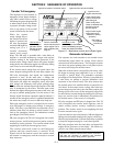
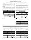
Figure 4-1. Controller cover latch.
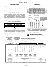
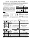
9volt
alkaline
battery
battery
on/off
jumper
retransfer
to normal
time delay
transfer to
emergency
time delay
harness
plugs
S3 DIP
switch
S1 DIP
switch
S2 DIP
switch
Figure 4-2. Location of potentiometers.
P1 or P2
potentiometer
clockwise to
increase
counterclockwise
to decrease
Figure 4-3. Changing time delay potentiometers.
DIP
switches
SW1
SW2
SW3
actuator
onoff
(8 on each DIP switch)
Figure 4-4. Setting DIP switch actuators.