


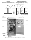
INSTALLATION (continued)
1-- 2
Controller Ground
A grounding wire must be connected to the controller’s
lower left mounting stud. Because the controller is
mounted on the enclosure door, a conductive strap must be
used between the enclosure and the door. This connection
provides proper grounding which does not rely upon the
door hinges.
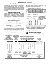
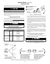
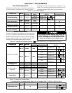
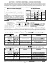
Engine Starting Contacts
Customer connections for engine control contact and TS
auxiliar y c on tac ts connection s are loc ated on ter m inal
bloc k TB which is mounted on the front l ower l eft of the
transfer sw itc h. Refer to wiring diag ram pr ovided with the
Series 300 ATS and connect the engine start wires to the
appropr iate term inal s. See Fig ure 1 –1 and Tab l e A.
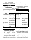
Table A. Engine start connections.
When normal
source fails
Ter mi na ls o n
transfer switch
contact closes TB1 and TB3
contact opens TB1 and TB2
Auxiliary Circuits
Connect auxiliary circuit wires to appropriate terminals on
transfer switch terminal block TB as shown on the wiring
diagram provided with this Series 300 Automatic Transfer
Switch. Make the necessary auxiliary connections by
referring to Section 5, Control Features.
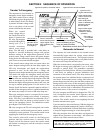
Harnesses
The transfer switch is connected to the left side of the
controller by a plug–in harness (two plugs).
TB Terminal Block
(field connections)
accepts wire range
22–12 AWG
Engine Starting
Signals
5amps,32VDC
5ampsresistive28VDC
or 120 V AC max.
TS Auxiliary Contacts
Feature 14A & 14B
10 amps, 32 V DC
10 amps 250V AC
general purpose
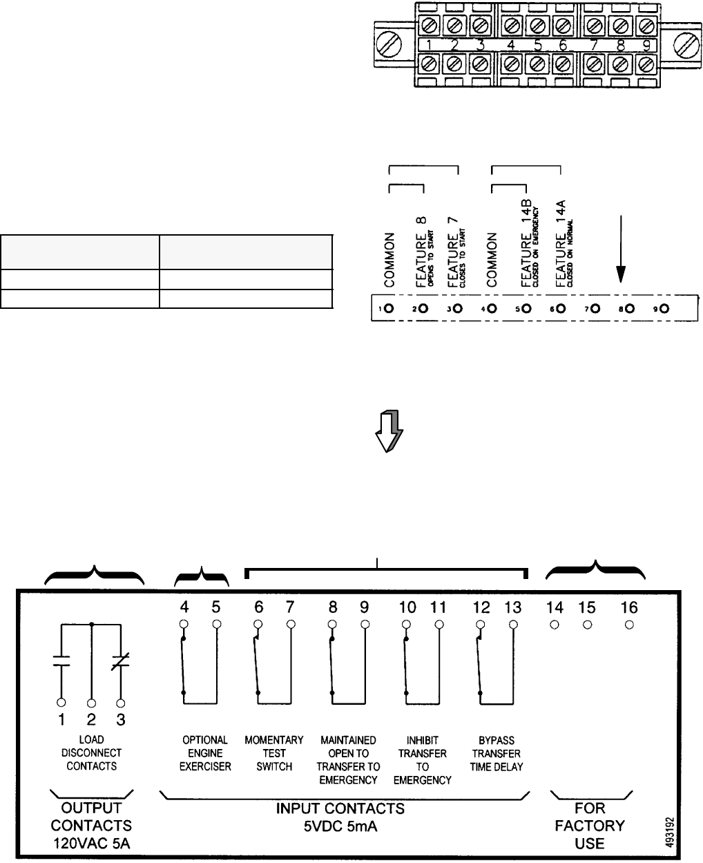
Figure 1-1. Connections to engine starting contact
terminal block l ocated on the Transfer Switch.
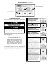
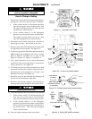
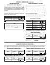
Connections to Controller
for other Control Features
(located on bottom of Controller)
for factory
use only
Remote Control Features Connections
(refer to the Wiring Diagram &
page 5–3 for DIP switch settings)
Each control contact must be suitable
for a 5 V DC low energy circuit.
Programmable
Engine Exerciser
connection,
if provided
(refer to
page 5–2)
Load Disconnect
Feature
Connections
(see W iring Diagram
& refer to page 5–3
for DIP switch settings)
Figure 1-2. Input / output label on the Controller showing possible connections to the lower terminal block.