


SECTION 1 INSTALLATION
1-- 1
ASCO Series 300 Automatic Transfer Switches (ATSs) are
Listed under Underwriters Laborat ories UL 1008
Standard for Safety for Automatic Transfer Switches. All
control features are UL Component Recognized, which
assures that ASCO automatic transfer switches meet
OSHA Safety Requirements and will be acceptable to
electrical inspectors.
ASCO Series 300 Automatic Transfer Switches aresuitable
for emergency and standby system applications. Theymeet
emergency system rating requirements as defined in
National Electrical Code (NEC) Article 700 and UL 1008.
Also, they are suitable for the require ments of NEC Article
517 – Health Care Facilities, NEC Article 701 – Legally
Required Standby Systems, NEC Article 702 – Optional
Standby Systems, NFPA 99 Health Care Facilities, and
NFPA 110 Emergency and Standby Power Systems.
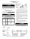
Rating Label
Eac h automatic transfer switc h contains a rating lab el to
define the loads and fault circuit withstand / c losing ratings.
Re fer to the l abel on the transfer sw itc h for spec ific v alu es.
Do not exceed the values on the rating label.
Exceeding the rating can cause personal injury
or serious equipment damage.
!
Series 300 Automatic Transfer Switches are factory wired
and tested. Installation requires skid removal then secur-
ing the enclosure to the supporting foundation.
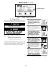
Remove the Shipping Skid
Open the front door and remove the four lag screws (twoi n
front, two in rear) securing the enclosure to the wood skid.
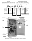
Supporting Foundation
The supporting foundation for the enclosure must be level
and straight. Refer to the applicable enclosure outline
drawing included with the Series 300 for all mounting
details including door opening space.
If bottom cable entry is used, the foundation must be
prepared so that the conduit stubs are located correctly.
Refer to the enclosure outline drawing for specified area
and location. Provide cable bending spaceand clearance to
live metal parts. When a concrete floor is poured, use
interlocking conduit spacer caps or a wood or metal
template to maintain proper conduit alignment.
Mounting
Refer to the applicable e nclosure outline drawing fur-
nished with this switch and mount the Series 300 according
to details and instructions shown on diagram.
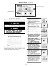
Auxiliary Cable Box for 1000–2000 amp
Anauxiliary cablebox isrequired if the powercables donot
enter the enclosure directly adjacent to the terminal lugs
(for example, if all power cables enter the top or bottom).
Order ASCO part no. 609027 if needed.
Do not route the power cables along
the sides of the Transfer Switch.
!
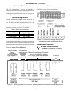
Line Connections
Refer to the Wiring Diagram provided wit h your Series 300
ATS. All wiring must be made in accordance with the
National Electrical Code and local codes.
It is unnecessary to remove pole covers from the transfer
switch. If you do remove them, reinstall them carefully.
De–energize t he conductors before making any
line or auxiliary circuitry connections. Be sure
that Normal and Emergency line connections
are in proper phase rotation. Place engine gen-
erator starting control in the OFF position. Make
sure engine generator is not in operation.
Testing Power Conductors
Do not connect the power conductors to the ASCO Series
300 transfer switch until they are tested. Installing power
cables in conduit, cable troughs and ceiling-suspended
hangers often requires considerable force. The pulling of
cables can damage insulation and stretch or break the
conductor’s strands. For this reason, after the cables are
pulled into position, and before
they are connected, they
should be tested to verify that they are not defective or
have been damaged during installati on.
Protect t he automatic t ransfer switch from
construction grit and metal chips to prevent
malfunction or shortened life of the ATS.
!
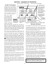
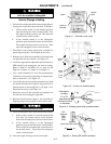
Connecting Power Conductors
After the power cables have been tested, connect them to
the appropriate terminal lugs on the transfer switch as
shown on the wiring diagram provided with this Series 300.
Make sure the lugs provided are suitable for use with the
cables being installed. Standard terminal lugs are solder-
less screw type and will accept the wire sizes listed on the
drawings provided with the Series 300. Be careful when
stripping insulation from the cables; avoid nicking or
ringing the conductor. Remove surface oxides from cables
by cleaning with a wire brush. When aluminum cable is
used, apply joint compound to conductors. Tighten cable
lugs to the torque specified on rating label.