


INSTALLATION (continued)
1-- 4
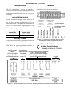
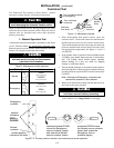
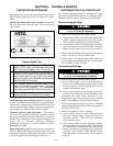
PressuntillightFLASHES
Pressfor15Seconds
Florh am Park NJ 07932 U SA
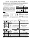
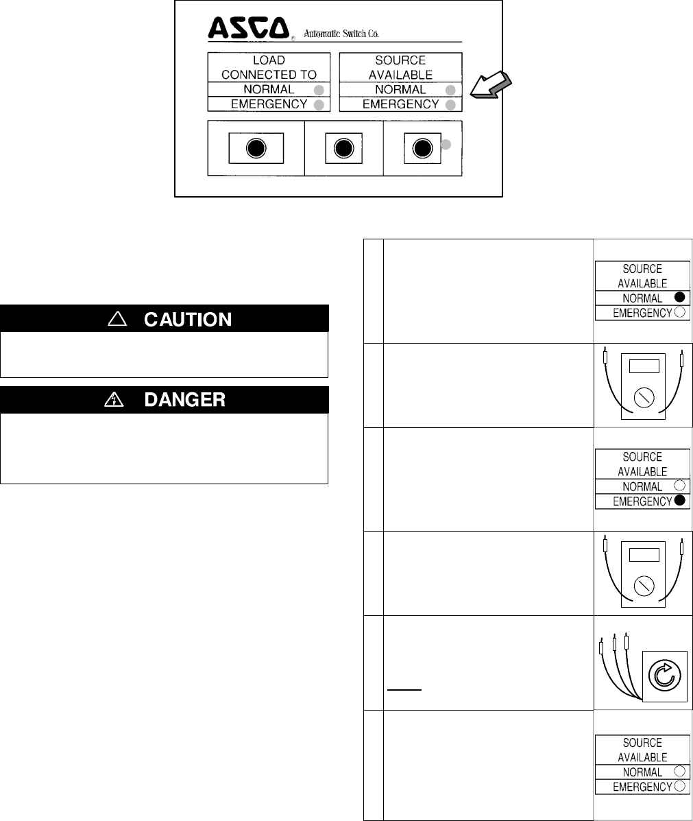
TRANSFER SWITCH TEST BYPASS TIMEDELAY SETENGINEEXERCISER
observe these lights
Figure 1–5. Standard controls and indicators.
2–VoltageChecks
First check nameplate on transfer switch; rated voltage
mustbethesameasnormalandemergencylinevoltages.
Verify that the feeders have been
connected to the proper lugs.
!
Use extreme caution when using a meter
to measure voltages in the following
steps. Do not touch power terminals;
sh oc k , burn s , or death cou ld res u lt !
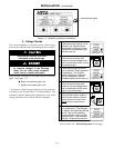
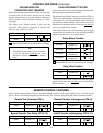
Perform steps 1 through 6 at the right. Observe the stat us
lights. See Figure 1–5.
● Black circle means light is on.
❍ White circle means light is off .
* If necessary, adjust voltage regulator on the generator
according to the manufacturer’s recommendations. The
Automatic Transfer Switch will respond only to the rated
voltage specified on the Transfer Switch nameplate.
1
Close the normal source circuit
breaker. The Transfer Switch
Connected To Normal and the
Normal Source A v ailable lights
should come on.
2
Use an accurate voltmeter to
check phase to phase and
phase to neutral voltages pres-
entatthetransferswitchnormal
source terminals.
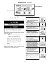
3
Close the emergency source
circuit breaker. (Start generator,
if necessary.) The Transfer
Switch Connected To Normal
and the Emergency Source
Available lights should come on.
4
Use an accurate voltmeter to
check phase to phase and
phase to neutral voltages pres-
ent at the transfer switch emer-
gency source terminals.*
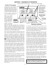
5
Useaphaserotationmeterto
check phase rotation of emer-
gency source; it must be the
same
as the normal source.
A
B
C
6
Shut down the engine–genera -
tor, if applicable. The Emergen-
cy Source Accepted light should
go off. Then put the starting
control selector switch (on the
generator set) in the automatic
position. Close enclosure door.
Now continue to 3 – Electrical Operation on next page.