


13
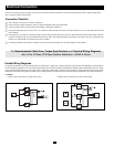
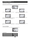
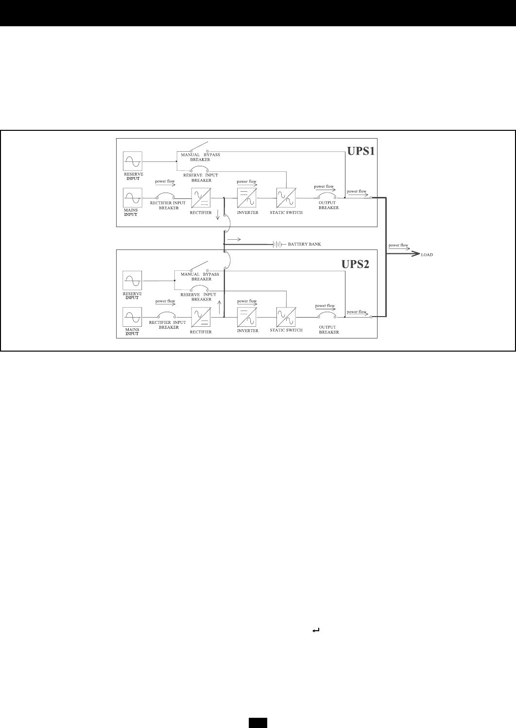
Multiple UPS Operation (Parallel)
(continued)
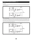
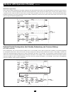
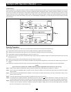
Common Battery
In this configuration, a single bank of battery modules is shared by multiple UPS power modules. This not only reduces installation costs, but saves
floor space. Note: when using the LCD Screen to set battery charging, divide the charging task equally among all UPS power modules. For example:
two UPS power modules are connected to a single bank of battery modules with a 100 amp-hour capacity. To charge the battery bank at a 12 amp
charge current rate, select a 6 amp “Battery Charge Current” setting and a 50 amp-hour “Battery Capacity AH” setting individually on each of the
LCD Screens of the two UPS power modules. Also note: in a Common Battery configuration, you will not be able to execute a battery test from
the LCD Screen.
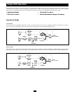
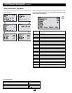
Start-Up Procedure
This procedure supplies power to and starts up the UPSs. Please check the following items before UPS start-up:
❑ Ensure that all electrical connections to all power modules and battery modules have been completed.
❑ Check that all circuit breakers and isolators are in the off position and battery fuse(s) have been removed.
❑ Ensure that the neutral line and grounding are at the same voltage level.
❑ Apply power to the AC input cables, and check that input voltage, frequency and phase sequence are within the specifications of the UPS and
the equipment load.
❑ Check to ensure auxiliary power and fan power (N) fuse isolators are closed.
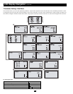
❑ Using the LCD Display Screen on each UPS power module within the parallel configuration, set the UPS ID. Set a different ID for each power
module.
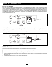
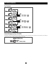
After following all warnings listed in the Safety section and precautions listed above, start-up UPSs according to the following procedure:
NOTE!
Apply each step to each UPS power module within the parallel configuration before moving on to the next step.
Step 1: Install external parallel communication cables between the parallel ports on the UPS power modules to a computer.
Step 2. Turn on (close) the “RESERVE INPUT” Breaker of each UPS power module. The LCD Screen on each UPS power module will display
“Bypass Mode”.
Step 3. Turn on (close) the “RECTIFIER INPUT” Breaker of each UPS power module and wait about 30 seconds. The DC BUS voltage will be
built up to about 393V DC.
Step 4. Locate the external fuse block(s) on the battery module(s) and turn on (close) the fuses.
Step 5. For each UPS power module individually, simultaneously press the “ON” and “ ” Buttons and hold for 3 seconds. The inverter will turn
on and voltage will build for about 30 seconds. The load will be transferred to the inverter. The LCD Screen will display “Normal Mode”.
Step 6. Measure the voltage on the UPS “OUTPUT” Breaker of each power module to determine if it is normal or abnormal. If the output voltage
is normal, turn on (close) the “OUTPUT” Breakers of each power module to supply power to the load. After approximately 30 seconds,
the UPS will automatically execute a battery test