


6
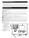
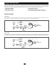
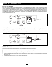
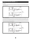
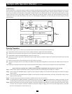
Parallel Wiring Diagrams
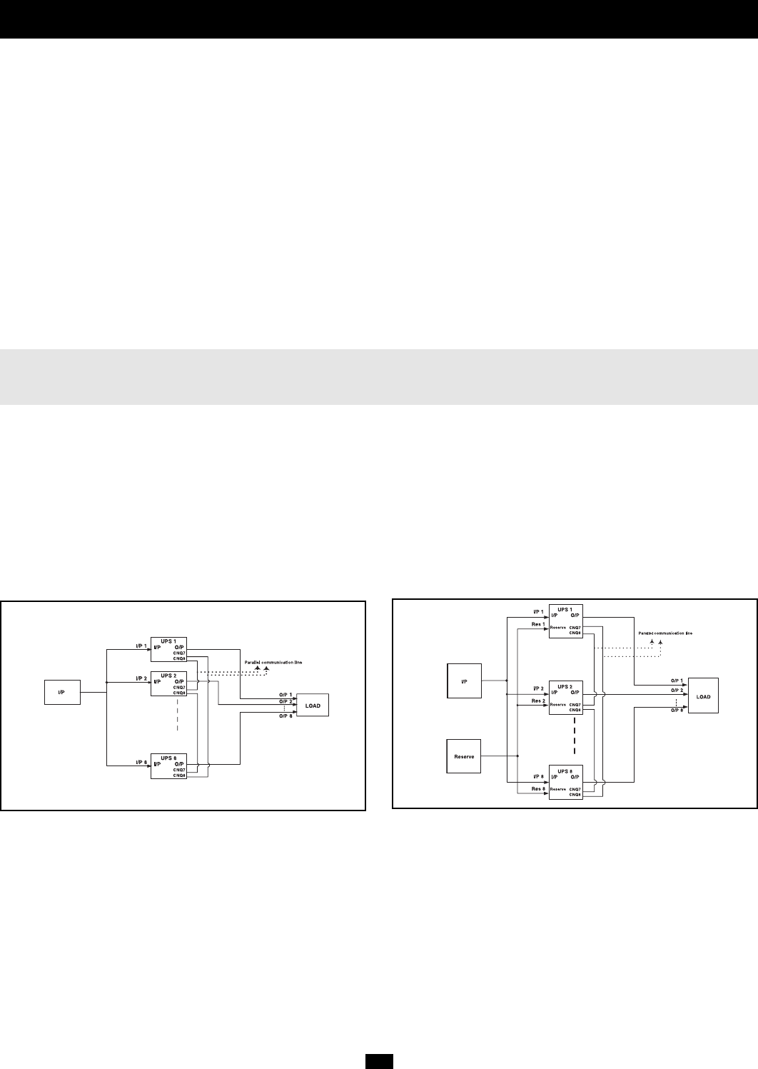
In a parallel connection, up to eight UPS Systems are connected to a single load. A parallel connection provides fail-safe redundancy, assuring that the
load is constantly supported even if one or more UPS Systems fail or are taken off-line for maintenance. Within a parallel architecture, there is a “single
loop” connection option (where only one input source is used) and a “double loop” connection option (where two input sources are used). Note: in both
connection options the total length of all cables (input, output and reserve) must be the same for each UPS Power Module to prevent load inequality.
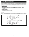
All Models
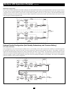
• Single Loop Connection (one input source used) • Double Loop Connection (two input sources used)
LOAD
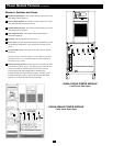
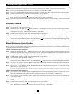
Electrical Connection
Follow all warnings listed in the Safety section prior to hardwire terminal connection. The following checklist provides a general guide rather
than a complete outline of procedures.
Connection Checklist
❑ Turn off input power prior to electrical connection.
❑ Check the input, output and battery cables for proper amplitude, phase and polarization.
❑ Connect ground wire(s) between UPS power module(s) and battery module(s).
❑ If the input and output power of the UPS is a Y connection, then note that the Neutral wire and Ground wire are not connected within the UPS
power module.
❑ If the input power system has a floating voltage between Neutral and Ground, and if 0 volts is desired between Neutral and Ground within the
UPS power module, Tripp Lite recommends the following: add a user-supplied isolation transformer to the input of the UPS, and connect the
Neutral wire and Ground wire inside the UPS power module.
❑ If installing multiple UPS modules in parallel, ensure input and output cables are the same length for each module.
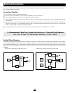
For Recommended Cable Sizes, Torque Specifications and Terminal Wiring Diagrams,
refer to the
3-Phase UPS Specifications Addendum—50kVA & Above.