


5
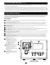
Power Module Features
(continued)
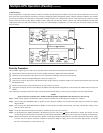
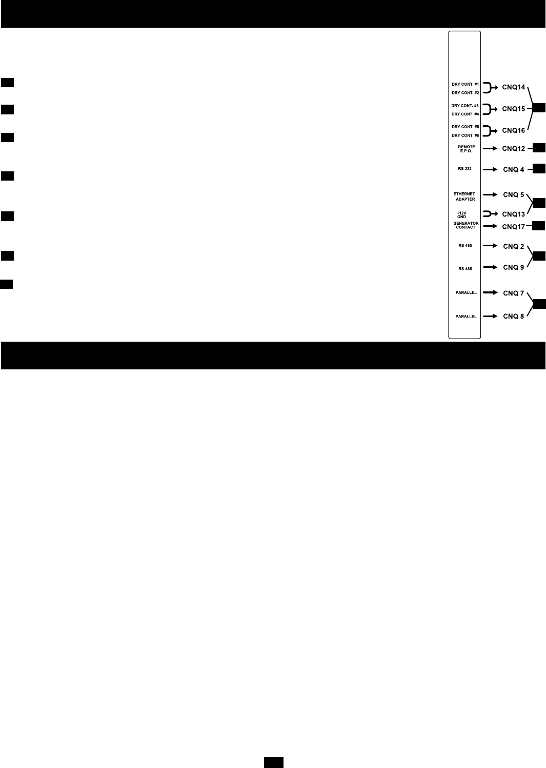
Communication Interface
Dry Contacts: #1 (UPS Normal); #2 (Load On Reserve); #3 (Load On Battery); #4 (Battery Low Voltage);
#5 (Reserve Abnormal); #6 (Battery Test Fail). See “Communications” for details.
Remote “Emergency Power OFF” (EPO) Connector: This modular jack allows remote emergency
shutdown. See “Communications” for details.
“Smart” RS-232 Interface Port: This female DB9 port connects the UPS to a workstation or server. It
uses RS-232 communications to report UPS and power conditions. It is used with Tripp Lite software and
cabling. See “Communications” for details.
Ethernet Port & Ethernet Power: The Ethernet Port is an RS-232 port that accepts an optional RS-232/RJ45
Ethernet Adapter (sold separately). The Ethernet Power connection provides 12VDC power to the
optional adapter. See “Communications” for details.
Generator Contact: This port connects to an auxiliary power generator. When the generator is operating
to support the equipment load, the UPS System will automatically reduce its charge current by 50% in order
to prevent overloading of the generator. See “Communications” for details.
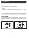
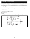
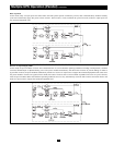
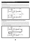
RS-485 Ports: These ports allow multiple UPS power modules to be connected in a parallel configuration.
See “Communications” for details.
UPS Parallel Communication Ports: These ports allow multiple UPS power modules to communicate
while in a parallel configuration. See “Communications” for details.
22
23
24
26
27
22
23
24
25
26
27
28
25
28
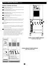
Installation
Follow all warnings listed in the Safety section prior to installation. The following checklist provides a general guide rather than a complete outline
of procedures.
Installation Checklist
❑ The floor area where the UPS will be installed has enough supporting strength. See Floor Weight Loading Table on the 3-Phase
UPS Specifications Addendum—50kVA & Above.
❑ The entrances and hallways to the facility provide enough room for UPS transportation.
❑ The room where the UPS will be installed has enough clearance around the UPS modules to allow adequate ventilation and access for operation
and maintenance.
❑ The facility's air conditioning can maintain ideal temperature and humidity levels.
❑ Noise abating devices are installed (if desired).
❑ Electrical wiring is clearly marked (for polarity and phase) and checked for compliance with local electrical codes.
❑ The input power source has been switched off prior to hardwire connection.
❑ The room where the UPS will be installed includes floor, ceiling and walls made of flameproof materials. The room includes a fire
extinguisher. The room is secure from access by unauthorized personnel.
❑ All personnel are sufficiently trained for normal and emergency operations.
❑ During installation, the UPS input neutral is solidly connected to the utility power neutral.