


3
Important Safety Warnings
(continued)
• Connect only Tripp Lite battery modules to the UPS's external battery hardware terminals.
• Do not operate the UPS without batteries.
• Fuses should be replaced only by factory authorized personnel. Blown fuses should be replaced only with fuses of the same number and type.
• Potentially lethal voltages exist within the UPS as long as the battery supply is connected. Service and repair should be done only by trained
personnel. During any service work, the UPS should be turned off or put into manual bypass and fuses removed from all connected battery modules.
• Do not connect or disconnect the battery modules while the UPS is operating from the battery supply or when the unit is not in bypass mode.
Power Module Features
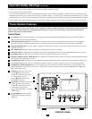
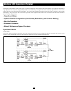
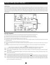
There are two separate UPS system modules: a power module and a battery module. Familiarize yourself with the location and function
of the features on each module before installing and operating the UPS system. The power module is described below. The battery
module is described in a separate manual.
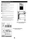
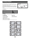
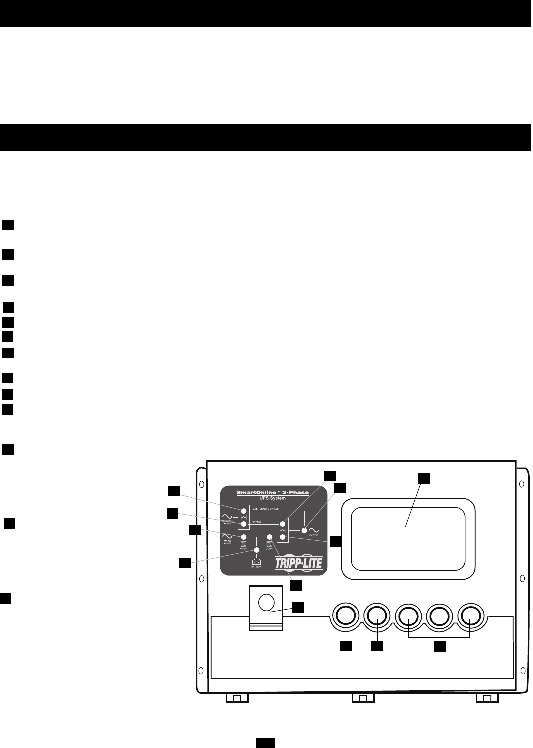
Control Panel
LCD Display: This backlit display indicates a wide range of UPS operating conditions and diagnostic data. It will illuminate after the
UPS has been properly installed and started up.
MAINTENANCE BYPASS LED: This red LED will illuminate when the UPS is providing filtered mains power without engaging its
converter or inverter. Connected equipment will not receive battery power in the event of a blackout when this light is illuminated.
RESERVE POWER LED: This green LED will illuminate to indicate the presence of a reserve power breaker and reserve power source
connected to the UPS.
RECTIFIER LED: This green LED will illuminate to indicate the UPS rectifier is operating.
BATTERY LED: This orange LED will illuminate when the UPS is discharging the battery to provide connected equipment with AC power.
INVERTER LED: This green LED will illuminate constantly to indicate the UPS inverter is activated.
RESERVE POWER STATIC SWITCH LED: This green LED will illuminate when the UPS is powering connected equipment through a
reserve power source connected to the UPS.
INVERTER MC LED: This green LED will illuminate to indicate connected equipment is supplied with power through the UPS inverter.
AC OUTPUT LED: This green LED will illuminate constantly to indicate your UPS is supplying AC power to connected equipment.
EMERGENCY POWER OFF Button: In case of emergency, press this button to turn off the UPS rectifier, inverter and output. After
pressing the button, it will remain down until reset. To reset the UPS system and restore output, press the EMERGENCY POWER OFF
button until it pops back up.
ON Button: This button, when used
with the
button, turns the UPS
inverter on. To turn the UPS inverter
on, simultaneously press the
ON and
buttons and hold for 3
seconds before releasing.
OFF Button: This button, when used
with the
button, turns the UPS
inverter off. To turn the inverter off,
simultaneously press the OFF
and
buttons and hold for 3 seconds
before releasing.
,
and
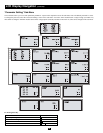
Buttons: These buttons
control the LCD Display and setting
parameters.
13
12
11
10
9
8
7
6
5
4
3
2
1
10
11 12
13
1
2
3
4
5
7
CONTROL PANEL
8
9
6