


14
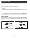
Multiple UPS Operation (Parallel)
(continued)
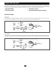
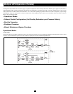
Shutdown Procedure
This procedure removes power from and shuts down the UPS power modules.
WARNING!
When shutting down individual UPS power modules in a parallel configuration, the user must ensure that the UPS power modules
within the configuration that remain ON can collectively power the equipment load. If they cannot, the UPS power modules within the
parallel configuration will be overloaded and will shut down and cease powering the equipment load.
NOTE!
Apply each step to each UPS power module within the parallel configuration before moving on to the next step.
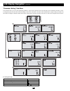
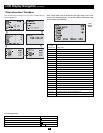
Step 1. For each UPS power module in the parallel configuration which will be shut down, simultaneously press the “OFF” and “ ” Buttons and
hold for 3 seconds. The power module's inverter will turn off; its LCD Screen will display “Output Close” and support of the equipment
load will be transferred and shared equally among the other UPS power modules in the parallel configuration that have not yet been shut
down. As each consecutive power module's inverter is turned off, however, a point will be reached where the power modules which have
not yet been shut down will not be able to share the combined load. At this point, the remaining power modules will automatically shut
down their inverters, transfer the load to reserve power and display “Bypass Mode” on their LCD Screens.
Step 2. Locate the external fuse block(s) on the battery module(s) and turn off (open) the fuses.
Step 3. Turn off (open) the “RECTIFIER INPUT” Breaker and “UPS OUTPUT” Breaker of each UPS power module.
Step 4. Wait approximately 5 minutes for the DC capacity to discharge. Press the “ON” and “OFF” Buttons of each UPS power module to test the
inverter for adequate discharge of DC capacity. Then, for each UPS power module in turn, simultaneously press the “OFF” and “ ”
Buttons to turn off their inverter. Confirm that BUS voltage is safe.
Step 5. Turn off (open) the “RESERVE INPUT” Breaker of each UPS power module.
Manual Maintenance Bypass Procedure
This procedure allows for routine maintenance by qualified service personnel. Tripp Lite recommends a routine maintenance inspection every six
months. Note: since the power modules' inverters are bypassed during this procedure, the UPSs will not be able to switch to Back-Up Mode and
support connected equipment in the event of a power failure.
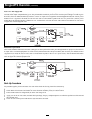
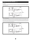
Manual Maintenance Procedure (ON Bypass)
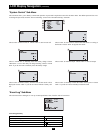
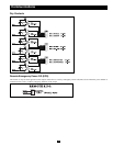
Step 1. For each UPS power module in the parallel configuration which will be placed on bypass, simultaneously press the “OFF” and “ ” Buttons
and hold for 3 seconds. The power module's inverter will turn off; its LCD Screen will display “Output Close” and support of the equipment
load will be transferred and shared equally among the other UPS power modules in the parallel configuration that have not yet been
placed on bypass. As each consecutive power module's inverter is turned off, however, a point will be reached where the power modules
which have not yet been placed on bypass will not be able to share the combined load. At this point, the remaining power modules will
automatically shut down their inverters, transfer the load to reserve power and display “Bypass Mode” on their LCD Screens.
Step 2. Locate the external fuse block(s) on the battery module(s) and turn off (open) the fuses.
Step 3. Turn off (open) the “RECTIFIER INPUT” Breaker of each UPS power module.
Step 4. Wait approximately 5 minutes for the DC capacity to discharge. Press the “ON” and “OFF” Buttons of each UPS power module to test the
inverter for adequate discharge of DC capacity. Then, for each UPS power module in turn, simultaneously press the “OFF” and “ ” Buttons
to turn off their inverter. Confirm that BUS voltage is safe.
Step 5. Turn on (close) the “MANUAL BYPASS” Breaker of each UPS power module. Support of the equipment load will transfer to manual
bypass. The LCD Screen of each UPS power module will display “Manual Bypass”.
Step 6. Turn off (open) the “UPS OUTPUT” Breaker, the “RESERVE INPUT” Breaker and the auxiliary power (+) and fan power (N) fuse
isolators of each UPS power module. The LCD Screens will go dark.
Note: When the UPSs are in Maintenance Bypass Mode, no high voltages will be present within the UPS power modules except at the terminals and the “MANUAL BYPASS” Breakers.
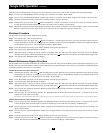
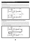
Manual Maintenance Procedure (OFF Bypass):
Step 1. Turn on (close) the “UPS OUTPUT” Breaker, the “RESERVE INPUT” Breaker and the auxiliary power (+) and fan power (N) fuse
isolators of each UPS power module. Support of the equipment load will transfer to manual bypass. The LCD Screens will display “Manual Bypass”.
Step 2. Turn off (open) the “MANUAL BYPASS” Breaker of each UPS power module. Support of the equipment load will transfer to reserve
power. The LCD Screens will display “Bypass Mode”.
Step 3. Turn on (close) the “RECTIFIER INPUT” breaker of each UPS power module and wait approximately 30 seconds.
Step 4. Locate the external fuse block(s) on the battery module(s) and turn on (close) the fuses.
Step 5. For each UPS power module to be taken off bypass, simultaneously press the “ON” and “ ” Buttons and hold for 3 seconds. The inverter
will turn on and voltage will build for about 30 seconds. The load will be transferred to the inverter. The LCD Screens will display “Normal Mode”.
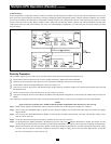
Step 6. Measure the voltage on the UPS “OUTPUT” Breaker of each power module to determine if it is normal or abnormal. If the output voltage
is normal, turn on (close) the “OUTPUT” Breakers of each power module to supply power to the load. After approximately 30 seconds,
the UPS will automatically execute a battery test.