


9
Basic Operation
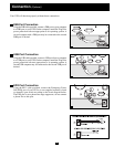
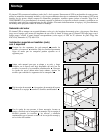
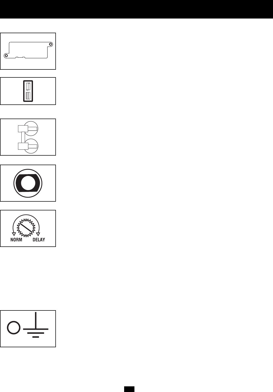
Accessory Slot
Remove the small cover panel from this slot to install optional accessories to remotely monitor
and control your UPS. Refer to your accessory’s manual for installation instructions.
Contact Tripp Lite Customer Support at (773) 869-1234 for more information, including a
list of available SNMP, network management and connectivity products.
External Battery Connector
Use to connect your UPS to an external battery pack. The specifications section of this manual
lists the Tripp Lite external battery packs that are compatible with your model. Refer to the
instructions provided with the battery pack for complete connection information and safety
warnings.
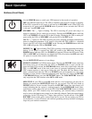
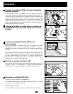
Input Breakers
Prevents high input current from damaging the UPS or the attached load. If this breaker
trips, make sure your UPS is connected to nominal 208V AC power before resetting the circuit
breaker by pushing the breaker levers to reset.
Output Breakers
Your UPS features 3 breakers that protect your UPS from output overload. If one or more
breakers trip, remove some of the load on the circuit(s) and allow the UPS to cool before
resetting the circuit(s) by pressing the breaker switch(es).
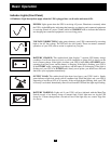
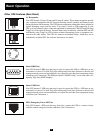
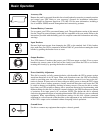
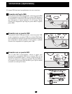
Power Sensitivity Adjustment
This dial is normally set fully counterclockwise, which enables the UPS to protect against
waveform distortions in its AC input. When such distortion occurs, the UPS will normally
switch to providing pure sine wave power from its battery reserves for as long as the dis-
tortion is present. In some such as in areas with poor utility power or where the UPS’s input
power comes from a backup generator, chronic waveform distortion could cause the UPS
to switch to battery too frequently, draining its battery reserves. You may be able to reduce
how often your UPS switches to battery due to waveform distortion by experimenting with
different settings for this dial. As the dial is turned clockwise, the UPS becomes more tolerant
of variations in its input power’s AC waveform. NOTE: The further the dial is adjusted
clockwise, the greater the degree of waveform distortion the UPS will allow to pass to connected
equipment. When experimenting with different settings for this dial, operate connected
equipment in a safe test mode so that the effect on the equipment of any waveform distortions
in the UPS’s output can be evaluated without disrupting critical operations.
Ground Screw
Use this to connect any equipment that requires a chassis ground.