


10
Features (Rear Panel)
continued
Battery Module Feature Description
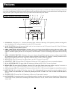
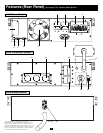
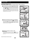
27. Input Connector (select Battery Modules only): Use this connector to daisy chain additional battery modules onto the first. Remove
the cover panel for access. Refer to the battery module owner’s manual for connection instructions and safety warnings.
28. Output Cable: Use this cable to connect the battery module to the power module or to another battery module. The power module will not start
without a connection to a charged battery module. Refer to the battery module owner’s manual for connection instructions and safety
warnings.
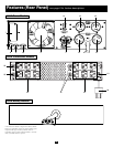
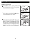
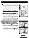
23. Input Voltage Select Switch (6kVA and 10kVA models only): Use this switch to set the transformer module's input voltage (either
200V AC, 208V AC or 240V AC). See “Connection” section for details.
24. AC Output Receptacles (5kVA models only): Accepts direct plug-in connection of NEMA 5-15P or NEMA 5-20P equipment plugs.
25. AC Output Breakers (5kVA models only): Push-button breakers control output power to transformer module's AC Output Receptacles
which are directly adjacent.
26. Cable for Power Module Connection (5kVA models only): Plugs directly into either of the 5kVA power module's AC Output 2
Receptacles. NOTE: this cable should only be plugged into the 5kVA power module.
Connection
• Wiring must be done by a qualified electrician.
• The UPS power module may be installed on its own or connected to an isolation transformer module. Both applications require the power module
to be connected to a battery module.
• When making wiring connections, observe the cable connection regulations appropriate to your area [e.g. National Electrical Code (NEC)
in the U.S.] at all times. Be sure to install an easily accessible disconnect switch in your installation wiring so you may cut off the UPS’s
AC input during fires and other emergencies. Ensure that cables are fitted with cable sleeves and are secured by connector clamps. Tighten
connections with a torque of not less than 24-28 inch-pounds (2.7-3.2 NM).
• Make sure that your equipment is properly grounded.
• Using cables of improper size may damage your equipment and cause fire hazards. Choose appropriate cabling and protection circuits to
make wiring connections (Ground conductors must be the same size and type as the power conductors used):
RATED INPUT CURRENT RATED OUTPUT CURRENT RATED OUTPUT CURRENT OUTPUT PROTECTION
200 - 240 (1Ø, 2-Wire + PE) 200 - 240V (1Ø, 2-Wire + PE) 120V (1Ø, 2-Wire + PE) CIRCUIT
6kVA Models 30A 8 AWG (10mm
2
) 30A 8 AWG (10mm
2
) 2 × 30A 8 AWG (10mm
2
) 30A
10kVA Models 50A 6 AWG (16mm
2
) 50A 6 AWG (16mm
2
) 2 × 50A 6 AWG (16mm
2
) 63A
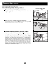
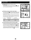
Hardwiring Cautions
(6kVA & 10kVA models only)
There are three separate UPS system modules available from Tripp Lite (a power module and a battery module, which are required in all
applications, and a transformer module) used in a variety of combinations. Follow the connection procedure below which matches the com-
bination of modules which you plan on installing.
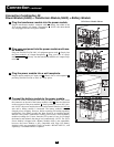
Connecting Modules to Each Other and to Utility Power and Equipment