


17
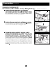
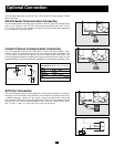
The following connections are optional. Your UPS system will function properly without
these connections.
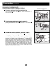
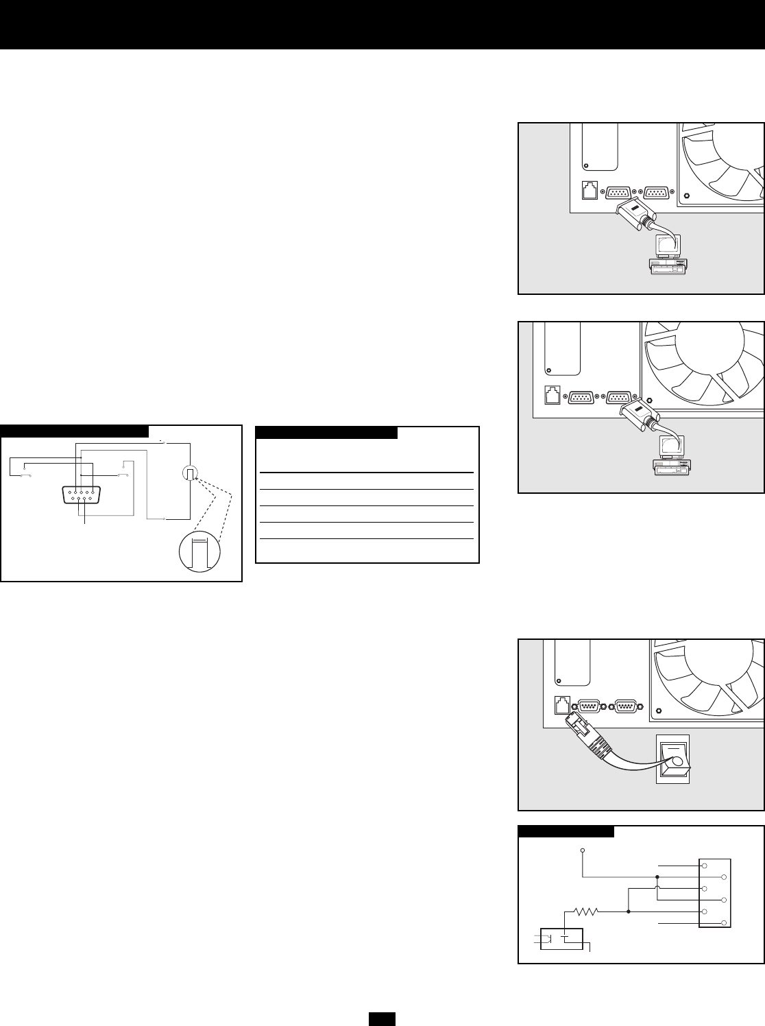
RS-232 Serial Communication Connection
Use the included cable to connect the power module’s “RS-232” port to the communication
port on your computer. This will allow full network monitoring and control of your
UPS system. Install on your computer the Tripp Lite PowerAlert Software appropriate
to your computer’s operating system.
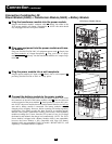
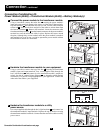
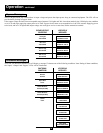
Contact-Closure Communication Connection
Use a user-supplied contact-closure DB9 cable to connect the power module’s “Dry-
Contact” port to the communication port on your computer or other equipment. This
will allow basic contact-closure signals to be sent to and from the UPS. Refer to the
following diagram and table to determine the signals carried by this port. Install on your
computer the Tripp Lite PowerAlert Software appropriate to your computer’s operating system.
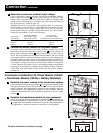
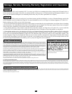
EPO Port Connection
This optional feature is only for those applications which require connection to a facility’s
Emergency Power Off (EPO) circuit. When the power module is connected to this circuit,
it enables emergency shutdown of the output. Using the included cable, connect the
power module’s EPO port to a user-supplied remote switch. The pin assignments for the
EPO port are shown in the following diagram. Note: if there is a short between pins 2
and 3, 2 and 5, 4 and 5, or 3 and 4, the UPS system will power off.
Optional Connection
0
12 V
>2 sec
54321
9
8
7
6
NO
COM NC
lm in. > 3.3 mA
BACK-UP
REMOTE SHUTDOWN SIGNAL
FROM EXTERNAL
SIGNAL FROM COMPUTER
COM NC
LOW BATTERY
NO
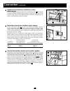
MAXIMUM CAPACITY OF DRY CONTACT: AC250V/3A • DC30V/3A
DRY CONTACT INTERFACE DIAGRAM
UPS Operating Pin 8,3 Pin 1,3 Pin 6,3
Mode
Normal OPEN OPEN *
Back Up CLOSE * *
Low Battery CLOSE CLOSE *
Fault * * CLOSE
* Inactive:may be in either state
DRY CONTACT INTERFACE TABLE
1
2
3
4
5
6
X
12V
X
1K
EPO PIN ASSIGNMENT