


14
Connection Combination #4:
Power Module (6kVA) + Transformer Module (6kVA) + Battery Module(s)
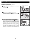
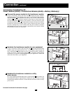
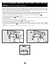
Connect the power module to the transformer module.
Using a screwdriver, remove the entire box covering the power module’s
input and output terminals. Remove the screws on either side of the terminals.
Grip the terminals and slide them out until you can view the cable connector
release tab . Press the tab down and pull on the cables to release them from
the internal connector . Remove the terminals. Insert the connector cable
from the transformer module into the internal connectors in the power module’s
terminal box until the release tab clicks in place. Replace the screws around
the plate. Although they are not needed, retain the power module’s terminals
and terminal box cover in case you plan to operate the power module without
the transformer module at a future date.
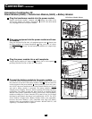
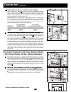
Hardwire the transformer module to your equipment.
Using a screwdriver, remove the top of the box covering the transformer
module’s input and output terminals. Pass a user-supplied cable through the
box’s left knockout and connect it to the transformer module’s output ter-
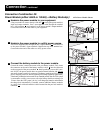
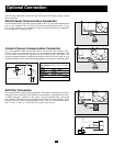
minals. See the AC Output Voltage Diagram to determine which terminal
connections will provide voltage appropriate to your application. Connect the
other end of the cable to your equipment.
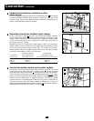
Hardwire the transformer module to a utility
power source.
Pass a user-supplied cable through the box’s right knockout and connect it to
the transformer module’s input terminals. Replace the top of the box covering
the transformer module’s terminals. Connect the other end of the cable to a utility
power source.
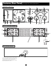
I
H
G
F
E
D
C
B
A
1
1
3
Connection
continued
N
O
R
M
A
L
BY
PAS
S
2
2
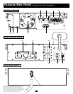
120V
240V
120V
208V
AC OUTPUT VOLTAGE DIAGRAM
G
N
O
R
M
A
L
BY
PAS
S
3
N
O
R
M
A
L
BY
PASS
1
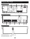
A
B
C
E
G
I
F
Connection Combination #4 continued on next page
H
D