


16
Connection
continued
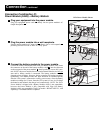
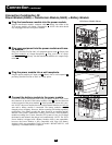
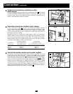
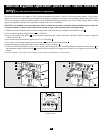
Hardwire the transformer module to a utility
power source.
Pass a user-supplied cable through the box’s middle knockout and connect
it to the transformer module’s input terminals. Connect the other end of the
cable to a utility power source. Replace the top of the boxes covering the power
module’s and transformer module’s terminals.
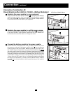
Select the transformer module’s input voltage.
Using a screwdriver, remove the panel covering the transformer module’s
Input Voltage Select Switch . Set the switch to match your facility’s input
voltage. Then, use the power module’s front panel switches to configure input
voltage on the LCD Display (see “Configure your UPS's input and output” in
the “Power ON/OFF” section).
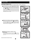
IMPORTANT NOTE: if your facility's input voltage is 200V AC, set the trans-
former module’s switch to 240V AC, but configure the power module to 200V
AC. If your facility’s input voltage is either 208V AC or 240V AC, the trans-
former module and power module settings must match. The factory default
settings for both modules is 208V. See chart below.
Transformer Module Power Module
Your Facility’s Input Voltage Setting Input Voltage Setting
Input Voltage (Rear Panel Switch) (Front Panel Switches/LCD Display)
240V AC 240V AC 240V AC
208V AC 208V AC 208V AC
200V AC 240V AC 200V AC
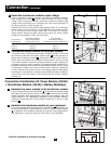
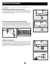
Connect the battery module to the power module.
Consult the owner’s manual that came with your battery module. Fully insert
the connector on the end of the battery module’s cable into the connector
on the rear panel of the power module . Small sparks may occur; this is normal.
NOTE: the power module does not contain internal batteries and will not supply
power to connected equipment until a battery module is connected. The battery
modules are fully charged prior to shipping. However, if the battery module
has been stored for an extended period, after the UPS system is connected to a
utility power source, allow the battery module to recharge for 12 hours. If
needed, connect additional battery modules in a daisy-chain with each module’s
cable inserted into the previous module’s connector .
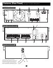
J
I
H
G
F
3
N
O
R
M
A
L
B
Y
PA
S
S
3
4
N
O
R
M
A
L
BY
PAS
S
5
5
F
NORMAL
BY
PASS
240V AC
208V AC
4
G
H
I
J